Southwest Wire Rope Products
Professional Rigging Made for Professionals
- Wire Rope
- Wire Rope Fittings
- Wire Rope Slings
- Chains
- Synthetic Web and Round Slings
- Straightpoint Load Monitoring Products

- Wire Rope
- Wire Rope Slings
- Chains
- Synthetic Web Slings
- Synthetic Round Slings
- Synthetic Rope
- Hardware
- General Purpose
- Crane
- 6 x 19
- 6 x 36
- 6 x 36 – Large Diameter
NOMINAL STRENGTHS OF WIRE ROPE
6 x 19 Classification/Bright (Uncoated),
or Drawn-Galvanized, Fiber Core, EIPS
|
Nom. Diam. |
Nominal Strength |
Approx. Mass |
|---|---|---|
|
Inches |
EIPS |
Lb/Ft |
Tons |
||
|
1/4 |
3.02 |
0.11 |
|
5/16 |
4.69 |
0.16 |
|
3/8 |
6.72 |
0.24 |
|
7/16 |
9.10 |
0.32 |
|
1/2 |
11.8 |
0.42 |
|
9/16 |
14.9 |
0.53 |
|
5/8 |
18.3 |
0.66 |
|
3/4 |
26.2 |
0.95 |
|
7/8 |
34.4 |
1.29 |
|
1 |
46.0 |
1.68 |
|
1 1/8 |
57.8 |
2.13 |
|
1 1/4 |
71.1 |
2.63 |
|
1 3/8 |
85.5 |
3.18 |
|
1 1/2 |
101 |
3.78 |
|
1 5/8 |
118 |
4.44 |
|
1 3/4 |
137 |
5.15 |
|
1 7/8 |
156 |
5.91 |
|
2 |
176 |
6.72 |
|
2 1/8 |
197 |
7.59 |
|
2 1/4 |
220 |
8.51 |
6 x 19 Classification/Bright (Uncoated),
or Drawn-Galvanized, IWRC, EIPS
|
Nom. Diam. |
Nominal Strength |
Approx. Mass |
|---|---|---|
|
Inches |
EIPS |
Lb/Ft |
| Tons | ||
|
1/4 |
3.40 |
0.12 |
|
5/16 |
5.27 |
0.18 |
|
3/8 |
7.55 |
0.26 |
|
7/16 |
10.2 |
0.35 |
|
1/2 |
13.3 |
0.46 |
|
9/16 |
16.8 |
0.59 |
|
5/8 |
20.6 |
0.72 |
|
3/4 |
29.4 |
1.04 |
|
7/8 |
39.8 |
1.42 |
|
1 |
51.7 |
1.85 |
|
1 1/8 |
65.0 |
2.34 |
|
1 1/4 |
79.9 |
2.89 |
|
1 3/8 |
96.0 |
3.50 |
|
1 1/2 |
114 |
4.16 |
|
1 5/8 |
132 |
4.88 |
|
1 3/4 |
153 |
5.67 |
|
1 7/8 |
174 |
6.50 |
|
2 |
198 |
7.39 |
|
2 1/8 |
221 |
8.35 |
|
2 1/4 |
247 |
9.36 |
|
2 3/8 |
274 |
10.4 |
|
2 1/2 |
302 |
11.6 |
|
2 5/8 |
331 |
12.8 |
|
2 3/4 |
361 |
14.0 |
(Meets or exceeds federal specification RR-W-41O [latest revision].)
NOMINAL STRENGTHS OF WIRE ROPE
6 x 36 Classification/Bright (Uncoated),
or Drawn-Galvanized, Fiber Core, EIPS
|
Nom. Diam. |
Nominal Strength |
Approx. Mass |
|---|---|---|
|
Inches |
EIPS |
Lb/Ft |
|
Tons |
||
|
1/4 |
3.02 |
0.11 |
|
5/16 |
4.69 |
0.16 |
|
3/8 |
6.72 |
0.24 |
|
7/16 |
9.10 |
0.32 |
|
1/2 |
11.8 |
0.42 |
|
9/16 |
14.9 |
0.53 |
|
5/8 |
18.3 |
0.66 |
|
3/4 |
26.2 |
0.95 |
|
7/8 |
34.4 |
1.29 |
|
1 |
46.0 |
1.68 |
|
1 1/8 |
57.8 |
2.13 |
|
1 1/4 |
71.1 |
2.63 |
|
1 3/8 |
85.5 |
3.18 |
|
1 1/2 |
101 |
3.78 |
|
1 5/8 |
118 |
4.44 |
|
1 3/4 |
137 |
5.15 |
|
1 7/8 |
156 |
5.91 |
|
2 |
176 |
6.72 |
|
2 1/8 |
197 |
7.59 |
|
2 1/4 |
220 |
8.51 |
6 x 36 Classification/Bright (Uncoated),
or Drawn-Galvanized, IWRC, EIPS
|
Nom. Diam. |
Nominal Strength |
Approx. Mass |
|---|---|---|
|
Inches |
EIPS |
Lb/Ft |
|
Tons |
||
|
1/4 |
3.40 |
0.12 |
|
5/16 |
5.27 |
0.18 |
|
3/8 |
7.55 |
0.26 |
|
7/16 |
10.2 |
0.35 |
|
1/2 |
13.3 |
0.46 |
|
9/16 |
16.8 |
0.59 |
|
5/8 |
20.6 |
0.72 |
|
3/4 |
29.4 |
1.04 |
|
7/8 |
39.8 |
1.42 |
|
1 |
51.7 |
1.85 |
|
1 1/8 |
65.0 |
2.34 |
|
1 1/4 |
79.9 |
2.89 |
|
1 3/8 |
96.0 |
3.50 |
|
1 1/2 |
114 |
4.16 |
|
1 5/8 |
132 |
4.88 |
|
1 3/4 |
153 |
5.67 |
|
1 7/8 |
174 |
6.50 |
|
2 |
198 |
7.39 |
|
2 1/8 |
221 |
8.35 |
|
2 1/4 |
247 |
9.36 |
|
2 3/8 |
274 |
10.4 |
|
2 1/2 |
302 |
11.6 |
|
2 5/8 |
331 |
12.8 |
|
2 3/4 |
361 |
14.0 |
|
2 7/8 |
392 |
15.3 |
|
3 |
425 |
16.6 |
|
3 1/8 |
458 |
18.0 |
|
3 1/4 |
492 |
19.5 |
|
3 3/8 |
529 |
21.0 |
|
3 1/2 |
564 |
22.7 |
|
3 5/8 |
602 |
24.3 |
|
3 3/4 |
641 |
26.0 |
(Meets or exceeds federal specification RR-W-41O [latest revision].)
6 x 36 Large Diameter
LARGE DIAMETER, HIGH STRENGTH
Specifications per API 9A
EEEIPS & Higher Grades are available on special order.
6 x 36 Classification Wire Rope Bright (Uncoated)
or Drawn-Galvanized Wire, Independent Wire Rope Core (IWRC)
|
Nominal |
Diameter |
Approximate |
Minimum |
||||
|---|---|---|---|---|---|---|---|
|
mm |
(in) |
min. mm |
max. mm |
kg/100 m |
(lb/ft) |
kN |
(short tons) |
|
63.5 |
(2 1/2) |
63.5 |
66.7 |
1,730 |
(11.6) |
2,950 |
(332) |
|
66.7 |
(2 5/8) |
66.7 |
70.0 |
1,910 |
(12.8) |
3,240 |
(364) |
|
69.9 |
(2 3/4) |
69.9 |
73.4 |
2,080 |
(14.0) |
3,530 |
(397) |
|
73.0 |
(2 7/8) |
73.0 |
76.7 |
2,280 |
(15.3) |
3,840 |
(432) |
|
76.2 |
(3) |
76.2 |
80.0 |
2,470 |
(16.6) |
4,160 |
(468) |
|
79.4 |
(3 1/8) |
79.4 |
83.4 |
2,680 |
(18.0) |
4,490 |
(505) |
|
82.6 |
(3 1/4) |
82.6 |
86.7 |
2,900 |
(19.5) |
4,830 |
(543) |
|
85.7 |
(3 3/8) |
85.7 |
90.0 |
3,130 |
(21.0) |
5,180 |
(582) |
|
88.9 |
(3 1/2) |
88.9 |
93.3 |
3,380 |
(22.7) |
5,520 |
(621) |
|
95.3 |
(3 3/4) |
95.3 |
100 |
3,870 |
(26.0) |
6,270 |
(705) |
|
102 |
(4) |
102 |
107 |
4,400 |
(44.0) |
6,340 |
(713) |
|
108 |
(4 1/4) |
108 |
113 |
4,960 |
(49.6) |
7,110 |
(799) |
|
114 |
(4 1/2) |
114 |
120 |
5,570 |
(55.7) |
7,900 |
(888) |
|
121 |
(4 3/4) |
121 |
127 |
6,200 |
(62.1) |
8,730 |
(981) |
|
127 |
(5) |
127 |
133 |
6,870 |
(68.8) |
9,590 |
(1,078) |
|
133 |
(5 1/4) |
133 |
140 |
7,410 |
(49.8) |
9,960 |
(1,120) |
|
140 |
(5 1/2) |
140 |
147 |
8,110 |
(54.5) |
10,800 |
(1,219) |
|
146 |
(5 3/4) |
146 |
153 |
8,870 |
(59.6) |
11,700 |
(1,320) |
|
152 |
(6) |
152 |
160 |
9,680 |
(65.0) |
12,700 |
(1,426) |
- Maxipact
- Rotation Resistant
- Compacted
Maxipact Overview
Oliveira NR Maxipact PPI
Properties
- Swivel
- Compacted
- Lubricated
- Tolerance
Oliveira NR Maxipact PPI
Properties
- Swivel
- Compacted
- Lubricated
- Tolerance
- PPI
Applications
All cranes and performant lifting devices where non-rotating and high MBL ropes are required.
Recommended for offshore, deck cranes, and marine environment.
- Temperature range of use: -50°C to +100°C
- Temperature range of use for option PPI: -50°C to +80°C
- Option PPI – only available for diameter ≥ 13mm
- Please add 1.0% on the weight for ropes with PPI
- Available in ordinary lay and Lang’s lay
- Available in right hand and left hand
|
RCN |
Diameter Range |
Construction |
Num. of |
Num. of wires |
Num. of |
Average fill factor |
Average spin factor |
|---|---|---|---|---|---|---|---|
|
23-3 |
12,70 - 52 |
37xK7 |
18 |
259 |
126 |
0,716 |
0.85 (1960*) |
|
30 |
54 - 64 |
37xK19 |
18 |
710 |
342 |
0,726 |
0.83 (1960*) |
|
>31 |
66 - 70 |
37xK26 |
18 |
1092 |
468 |
0,714 |
0.81 (1960*) |
Rotation Resistant Types
19 x 7 Classification/Bright (Uncoated)
or Drawn-Galvanized Wire Strand Core
|
Nominal Diam. |
Nominal Strength |
Approx. Mass |
|---|---|---|
|
1/4 |
2.77 |
0.113 |
|
1/16 |
4.30 |
0.175 |
|
3/8 |
6.15 |
0.25 |
|
7/16 |
8.33 |
0.35 |
|
1/2 |
10.80 |
0.45 |
|
9/16 |
13.60 |
0.58 |
|
5/8 |
16.80 |
0.71 |
|
3/4 |
24.00 |
1.02 |
|
7/8 |
32.50 |
1.39 |
|
1 |
42.20 |
1.82 |
|
1 1/8 |
53.10 |
2.30 |
|
1 1/4 |
65.10 |
2.84 |
8 x 19 Classification/Bright (Uncoated),
or Drawn-Galvanized, IWRC (EIPS)
|
Nominal Diam. |
Nominal Strength |
Approx. Mass |
|---|---|---|
|
1/2 |
11.6 |
.47 |
|
9/16 |
14.7 |
.60 |
|
5/8 |
18.1 |
.73 |
|
3/4 |
25.9 |
1.06 |
|
7/8 |
35.0 |
1.44 |
|
1 |
45.5 |
1.88 |
Meets or exceeds applicable APl-9A and federal specification RR-W-410 (latest revision).
Compacted Strand
Mining, industrial, construction, logging, and oilfield applications.
Stability, strength, fatigue resistance, and abrasion resistance.
All popular sizes.
Longer service life.
Extra value means different things in different applications.
In applications where increased strength, stability, and abrasion resistance are beneficial. 6-strand compacted ropes are a natural and can result in longer service life. From boom hoist ropes and drag ropes in mining applications, to sawmill carriage ropes and mainline ropes in logging, their versatility and extra value make a difference.
As single-part hoist lines and wherever spooling problems, drum crushing, bird caging, block twisting and fast line speeds are likely to be encountered.
At the design and specification stage, ideal when machinery space and weight savings are important.
Greater fatigue resistance cuts rope expense in applications where fatigue is the primary cause for removal.
Ideally suited to rugged applications.
This rotation resistant, higher strength rope provides extra value in both original equipment designs and replacement applications. 18 and 19 strand compacted wire rope, provides higher strength in a smaller diameter, and resistance to drum crushing.
|
Nominal Diameter |
6 Strand |
** 19 X 19 and 18 X 19 |
||
|---|---|---|---|---|
|
Minimum Breaking Load |
Approx. Mass |
Minimum Breaking Load |
Approx. Mass |
|
|
3/ 18 |
8.30 |
.31 |
8.30 |
.31 |
|
7/16 |
11.2 |
.39 |
11.2 |
.40 |
|
1/2 |
14.6 |
.49 |
14.6 |
.54 |
|
9/16 |
18.5 |
.63 |
18.5 |
.69 |
|
5/8 |
22.7 |
.78 |
22.7 |
.85 |
|
3/4 |
32.4 |
1.13 |
32.4 |
1.25 |
|
7/8 |
43.8 |
1.54 |
43.8 |
1.68 |
|
1 |
56.9 |
2.00 |
56.9 |
2.17 |
|
1 1/8 |
71.5 |
2.54 |
71.5 |
2.75 |
|
1 1/4 |
87.9 |
3.14 |
87.9 |
3.45 |
|
1 3/8 |
106 |
3.80 |
106 |
4.33 |
|
1 1/2 |
125 |
4.50 |
125 |
5.11 |
Breaking loads listed are the minimum established by the Wire Rope Technical Board. Verify the breaking load when inquiring as actual inventories may have different breaking loads.
** The given strengths for 19 strand rotation resistant wire ropes are applicable only when a test is conduced on a new rope fixed at both ends. When the rope is in use and one end is free to rotate. the nominal strength is reduced.
Not recommended for use with swivels.
- Single Leg
- 2-leg
- 3-leg
- 4-leg
- Braided Slings
- End Fittings
- Mechanically Swaged
- Poured Sockets
- Open/Closed Swaged
Flemished Eye and Mechanically Swaged
| Diam. Of Wire Rope Inches | Min. Length (SL) Of Sling Ft.-In. | Inside Loop Dimensions | Rated Capacity in Tons (2000 lbs.) | |||
|---|---|---|---|---|---|---|
| EIPS-IWRC | ||||||
| Single Leg Vertical | Choker Hitch | Vertical Basket Hitch** | ||||
| W Inches | L Inches | |||||
|
1/4 |
1-6 |
2 |
4 |
.65 |
.48 |
1.3 |
|
5/16 |
1-9 |
2 1/2 |
5 |
1.00 |
.74 |
2.0 |
|
3/8 |
2-0 |
3 |
6 |
1.40 |
1.10 |
2.9 |
|
7/16 |
2-3 |
3 1/2 |
7 |
1.90 |
1.40 |
3.9 |
|
1/2 |
2-6 |
4 |
8 |
2.50 |
1.90 |
5.1 |
|
9/16 |
2-9 |
4 1/2 |
9 |
3.20 |
2.40 |
6.4 |
|
5/8 |
3-0 |
5 |
10 |
3.90 |
2.90 |
7.8 |
|
3/4 |
3-6 |
6 |
12 |
5.60 |
4.10 |
11.0 |
|
7/8 |
4-0 |
7 |
14 |
7.60 |
5.60 |
15.0 |
|
1 |
4-6 |
8 |
16 |
9.80 |
7.20 |
20.0 |
|
1 1/8 |
5-0 |
9 |
18 |
12.00 |
9.10 |
24.0 |
|
1 1/4 |
5-6 |
10 |
20 |
15.00 |
11.00 |
30.0 |
|
1 3/8 |
6-0 |
11 |
22 |
18.00 |
13.00 |
36.0 |
|
1 1/2 |
7-0 |
12 |
24 |
21.00 |
16.00 |
42.0 |
|
1 5/8 |
4-6 |
13 |
26 |
24.00 |
18.00 |
49.0 |
|
1 3/4 |
8-0 |
14 |
28 |
28.00 |
21.00 |
57.0 |
|
2 |
9-0 |
16 |
32 |
37.00 |
28.00 |
73.0 |
|
2 1/4 |
10-0 |
18 |
36 |
44.00 |
35.00 |
89.0 |
|
2 1/2 |
11-0 |
20 |
40 |
54.00 |
42.00 |
109.0 |
|
2 3/4 |
12-0 |
22 |
44 |
65.00 |
51.00 |
130.0 |
|
3 |
13-0 |
24 |
48 | 77.00 |
60.00 |
153.0 |
|
3 1/2 |
19-8 |
36 |
72 |
102.00 |
79.00 |
203.0 |
|
4 |
23-8 |
45 |
90 |
130.00 |
97.00 |
259.0 |
| Wire Rope Diam. Inches | Heavy Duty Thimble | Alloy Hook Size-Tons | Carbon Shackle Size-Inches | Open Swagged Socket | Closed Swaged Socket | |||
|---|---|---|---|---|---|---|---|---|
| Inside | For EIPS | For EIPS | Pin Size Inches | Jaw Size Inches | Hole Diam. Inches | Head Thickness Inches | ||
| Width Inches | Length Inches | |||||||
| 6 x 19 WITH I. W. R. C. | ||||||||
| 1/4 | 7/8 | 1 5/8 | 1 | 5/16 | 11/16 | 11/16 | 3/4 | 1/2 |
| 5/16 | 1 1/16 | 1 7/8 | 1 1/2 | 3/8 | 13/16 | 13/16 | 7/8 | 11/16 |
| 3/8 | 1 1/8 | 2 1/8 | 2 | 7/16 | 13/16 | 13/16 | 7/8 | 11/16 |
| 7/16 | 1 1/4 | 2 3/8 | 3 | 1/2 | 1 | 1 | 1 1/16 | 7/8 |
| 1/2 | 1 1/2 | 2 3/4 | 5 | 5/8 | 1 | 1 | 1 1/16 | 7/8 |
| 9/16 | 1 1/2 | 2 3/4 | 5 | 5/8 | 1 3/16 | 1 1/4 | 1 1/4 | 1 1/8 |
| 5/8 | 1 3/4 | 3 1/4 | 7 | 3/4 | 1 3/16 | 1 1/4 | 1 1/4 | 1 1/8 |
| 3/4 | 2 | 3 3/4 | 11 | 7/8 | 1 3/8 | 1 1/2 | 1 7/16 | 1 5/16 |
| 7/8 | 2 1/4 | 4 1/4 | 11 | 1 | 1 5/8 | 1 3/4 | 1 11/16 | 1 1/2 |
| 1 | 2 1/2 | 4 1/2 | 15 | 1 1/4 | 2 | 2 | 2 1/16 | 1 3/4 |
| 1 1/8 | 2 7/8 | 5 1/8 | 22 | 1 1/4 | 2 1/4 | 2 1/4 | 2 5/16 | 2 |
| 6 x 37 WITH I. W. R. C. | ||||||||
| 1 1/4 | 3 1/2 | 6 1/2 | 22 | 1 1/2 | 2 1/2 | 2 1/2 | 2 9/16 | 2 1/4 |
| 1 3/8 | 3 1/2 | 6 1/4 | 30 | 1 3/4 | 2 1/2 | 2 1/2 | 2 9/16 | 2 1/4 |
| 1 1/2 | 3 1/2 | 6 1/4 | 30 | 1 3/4 | 2 3/4 | 3 | 2 13/16 | 2 1/2 |
| 1 5/8 | 4 | 8 | 30 | 1 3/4 | - | - | - | - |
| 1 3/4 | 4 1/2 | 9 | 37 | 2 | 3 1/2 | 3 1/2 | 3 9/16 | 3 |
| 2 | 6 | 12 | 60 | 2 1/2 | 3 3/4 | 4 | 3 13/16 | 3 1/4 |
| 2 1/4 | 7 | 14 | 60 | 2 1/2 | - | - | - | - |
| 2 1/2 | 8 1/2 | 15 3/4 | - | 2 1/2 | - | - | - | - |
| 2 3/4 | - | - | - | 3 | - | - | - | - |
| 3 | - | - | - | 3 | - | - | - | - |
| 3 1/2 | - | - | - | 3 1/2 | - | - | - | - |
| 4 | - | - | - | 4 | - | - | - | - |
Design Factor 5:1
* Rated capacities of choker hitches apply when the angle of choke is greater than 135°.
**Rated capacities of basket hitches are based on a minimum diameter of curvature at the point of load contact of 20 times the rope diameter.
|
Diameter Of Wire Rope Inches |
Minimum Length (SL) Of Sling |
Rated Capacities in Tons (2,000 lbs.) |
Important Dimensions |
||||||
|---|---|---|---|---|---|---|---|---|---|
|
Open Socket |
Closed Socket |
||||||||
|
Single Part Vertical |
Vertical Basket |
O |
D |
W |
L |
K |
|||
|
1/4 |
1-0 |
.68 |
1.3 |
11/16 |
11/16 |
13/16 |
1 3/4 |
1/2 |
|
|
5/16 |
1-0 |
1.10 |
1.9 |
13/16 |
13/16 |
15/16 |
2 |
11/16 |
|
|
3/8 |
1-0 |
1.50 |
2.8 |
13/16 |
13/16 |
15/16 |
2 |
11/16 |
|
|
7/16 |
1-2 |
2.00 |
3.8 |
1 |
1 |
1 1/8 |
2 1/4 |
7/8 |
|
|
1/2 |
1-3 |
2.70 |
4.9 |
1 |
1 |
1 1/8 |
2 1/4 |
7/8 |
|
|
9/16 |
1-5 |
3.40 |
6.2 |
1 1/4 |
1 3/16 |
1 3/8 |
2 1/2 |
1 |
|
|
5/8 |
1-6 |
4.10 |
7.6 |
1 1/4 |
1 3/16 |
1 3/8 |
2 1/2 |
1 |
|
|
3/4 |
1-9 |
5.90 |
11 |
1 1/2 |
1 3/8 |
1 5/8 |
3 |
1 1/4 |
|
|
7/8 |
2-0 |
8.00 |
15 |
1 3/4 |
1 5/8 |
1 7/8 |
3 1/2 |
1 1/2 |
|
|
1 |
2-6 |
10.00 |
19 |
2 |
2 |
2 1/4 |
4 |
1 3/4 |
|
|
1 1/8 |
2-9 |
13.00 |
24 |
2 1/4 |
2 1/4 |
2 1/2 |
4 1/2 |
2 |
|
|
1 1/4 |
3-0 |
16.00 |
30 |
2 1/2 |
2 1/2 |
2 3/4 |
5 |
2 1/4 |
|
|
1 3/8 |
3-0 |
19.00 |
36 |
2 1/2 |
2 1/2 |
2 3/4 |
5 |
2 1/4 |
|
|
1 1/2 |
3-3 |
23.00 |
42 |
3 |
2 3/4 |
3 1/8 |
6 |
2 1/2 |
|
|
1 5/8 |
3-9 |
26.00 |
49 |
3 |
3 |
3 1/4 |
6 1/2 |
2 3/4 |
|
|
1 3/4 |
4-3 |
31.00 |
57 |
3 1/2 |
3 1/2 |
3 17/32 |
7 9/16 |
3 |
|
|
2 |
4-9 |
39.00 |
73 |
4 |
3 3/4 |
3 25/32 |
8 9/16 |
3 1/4 |
|
|
2 1/4 |
5-0 |
49.00 |
91 |
4 1/2 |
4 1/4 |
4 9/32 |
9 1/2 |
3 5/8 |
|
|
2 1/2 |
5-9 |
60.00 |
112 |
5 |
4 3/4 |
5 1/2 |
10 5/8 |
4 |
|
|
2 3/4 |
6-5 |
72.00 |
134 |
5 1/4 |
5 |
6 1/2 |
11 1/4 |
4 7/8 |
|
|
3 |
6-10 |
85.00 |
157 |
5 3/4 |
5 1/4 |
6 3/4 |
11 3/4 |
5 1/4 |
|
|
3 1/4 |
7-7 |
98.00 |
182 |
6 1/4 |
5 1/2 |
7 1/4 |
12 1/4 |
5 3/4 |
|
|
3 1/2 |
8-2 |
113.00 |
209 |
6 3/4 |
6 |
7 3/4 |
13 |
6 1/4 |
|
|
3 3/4 |
8-8 |
128.00 |
235 |
7 1/2 |
7 |
8 1/4 |
14 |
7 |
|
|
4 |
9-1 |
143.00 |
263 |
7 1/2 |
7 |
8 1/4 |
14 |
7 |
|
|
Design Factor 5:1 |
|||||||||
|
Diameter Of Wire Rope Inches |
Minimum Length (SL) Of Sling |
Rated Capacities in Tons (2,000 lbs.) |
Important Dimensions |
||||||
|---|---|---|---|---|---|---|---|---|---|
|
Open Swage Socket |
Closed Swage Socket |
||||||||
|
Single Part Vertical |
Vertical Basket |
O |
D |
W |
L |
K |
|||
|
1/4 |
0-11 |
.68 |
1.3 |
11/16 |
11/16 |
1 5/32 |
1/2 |
3/4 |
|
|
5/16 |
1-1 |
1.10 |
1.9 |
13/16 |
13/16 |
1 11/32 |
11/16 |
7/8 |
|
|
3/8 |
1-3 |
1.50 |
2.8 |
13/16 |
13/16 |
1 11/32 |
11/16 |
7/8 |
|
|
7/16 |
1-6 |
2.00 |
3.8 |
1 |
1 |
1 1/2 |
7/8 |
1 1/16 |
|
|
1/2 |
1-8 |
2.70 |
4.9 |
1 |
1 |
1 1/2 |
7/8 |
1 1/16 |
|
|
9/16 |
1-10 |
3.40 |
6.2 |
1 1/4 |
1 3/16 |
1 21/32 |
1 1/8 |
1 1/4 |
|
|
5/8 |
2-0 |
4.10 |
7.6 |
1 1/4 |
1 3/16 |
1 21/32 |
1 1/8 |
1 1/4 |
|
|
3/4 |
2-5 |
5.90 |
11 |
1 1/2 |
1 3/8 |
2 1/16 |
1 5/16 |
1 7/16 |
|
|
7/8 |
2-10 |
8.00 |
15 |
1 3/4 |
1 5/8 |
2 7/16 |
1 1/2 |
1 11/16 |
|
|
1 |
3-2 |
10.00 |
19 |
2 |
2 |
2 3/4 |
1 3/4 |
2 1/16 |
|
|
1 1/8 |
3-7 |
13.00 |
24 |
2 1/4 |
2 1/4 |
3 1/8 |
2 |
2 5/16 |
|
|
1 1/4 |
4-0 |
16.00 |
30 |
2 1/2 |
2 1/2 |
3 1/2 |
2 1/4 |
2 9/16 |
|
|
1 3/8 |
4-5 |
19.00 |
36 |
2 1/2 |
2 1/2 |
4 |
2 1/4 |
2 9/16 |
|
|
1 1/2 |
4-9 |
23.00 |
42 |
3 |
2 3/4 |
4 3/8 |
2 1/2 |
2 13/16 |
|
|
1 3/4 |
5-5 |
31.00 |
57 |
3 1/2 |
3 1/2 |
5 |
3 |
3 9/16 |
|
|
2 |
6-4 |
39.00 |
73 |
4 |
3 3/4 |
6 1/8 |
3 1/4 |
3 13/16 |
|
|
2 1/4 |
7-2 |
49.00 |
91 |
4 1/2 |
4 1/4 |
4 5/8 |
4 |
4 5/16 |
|
|
2 1/2 |
8-0 |
60.00 |
112 |
4 1/2 |
4 1/4 |
4 5/8 |
4 |
4 5/16 |
|
|
Design Factor 5:1 |
|||||||||
2-Leg - Type 21
FLEMISHED EYE AND MECHANICALLY SWAGED
Type 21 slings are 2-leg All-Purpose bridles, designed for general lifting purposes where attachment may be made directly to the load, such as hooking into lifting eyes or placing loops over lugs.
|
Diameter Of Wire Rope |
Minimum Length (SL) Of Sling |
Rated Capacities in Tons |
Alloy Links |
||||||
|---|---|---|---|---|---|---|---|---|---|
|
60° |
45° |
30° |
|||||||
|
1/4 |
1-3 |
1.10 |
.91 |
.65 |
1/2 |
||||
|
5/16 |
1-6 |
1.70 |
1.40 |
1.00 |
1/2 |
||||
|
3/8 |
1-8 |
2.50 |
2.00 |
1.40 |
3/4 |
||||
|
7/16 |
1-10 |
3.40 |
2.70 |
1.90 |
7/8 |
||||
|
1/2 |
2-0 |
4.40 |
3.60 |
2.50 |
1 |
||||
|
9/16 |
2-2 |
5.50 |
4.50 |
3.20 |
1 1/4 |
||||
|
5/8 |
2-4 |
6.80 |
5.50 |
3.90 |
1 1/4 |
||||
|
3/4 |
2-9 |
9.70 |
7.90 |
5.60 |
1 1/4 |
||||
|
7/8 |
3-3 |
13.00 |
11.00 |
7.60 |
1 1/2 |
||||
|
1 |
3-6 |
17.00 |
14.00 |
9.80 |
1 1/2 |
||||
|
1 1/8 |
4-0 |
21.00 |
17.00 |
12.00 |
1 3/4 |
||||
|
1 1/4 |
4-6 |
26.00 |
21.00 |
15.00 |
2 |
||||
|
1 3/8 |
5-0 |
31.00 |
25.00 |
18.00 |
2 |
||||
|
1 1/2 |
5-6 |
37.00 |
30.00 |
21.00 |
2 1/4 |
||||
|
1 5/8 |
6-0 |
42.00 |
35.00 |
24.00 |
2 1/2 |
||||
|
1 3/4 |
6-6 |
49.00 |
40.00 |
28.00 |
2 1/2 |
||||
|
2 |
8-0 |
63.00 |
52.00 |
37.00 |
2 3/4 |
||||
|
2 1/4 |
8-9 |
77.00 |
63.00 |
44.00 |
3 1/4 |
||||
|
2 1/2 |
10-0 |
94.00 |
77.00 |
54.00 |
3 3/4 |
||||
|
Design Factor 5:1 |
|||||||||
|
Wire Rope Diam. |
Standard Loop Inside |
Heavy Duty Thimble Inside |
Alloy Hook Size-Tons |
Carbon Shackle With Thimble Size-Inches |
Open Swaged Socket |
Closed Swaged Socket |
||||
|---|---|---|---|---|---|---|---|---|---|---|
|
Pin Size |
Jaw Size |
Hole Diam. |
Head Opening |
|||||||
|
Width Inches |
Length Inches |
Width Inches |
Length Inches |
|||||||
|
6 x 19 WITH I. W. R. C. |
||||||||||
|
1/4 |
2 |
4 |
7/8 |
1 5/8 |
1 |
5/16 |
11/16 |
11/16 |
3/4 |
1/2 |
|
5/16 |
2 1/2 |
5 |
1 1/16 |
1 7/8 |
1 1/2 |
3/8 |
13/16 |
13/16 |
7/8 |
11/16 |
|
3/8 |
3 |
6 |
1 1/8 |
2 1/8 |
2 |
7/16 |
13/16 |
13/16 |
7/8 |
11/16 |
|
7/16 |
3 1/2 |
7 |
1 1/4 |
2 3/8 |
3 1/2 |
1 |
1 |
1 |
1/16 |
7/8 |
|
1/2 |
4 |
8 |
1 1/2 |
2 3/4 |
5 |
5/8 |
1 |
1 |
1 1/16 |
7/8 |
|
9/16 |
4 1/2 |
9 |
1 1/2 |
2 3/4 |
5 |
5/8 |
1 3/16 |
1 1/4 |
1 1/4 |
1 1/8 |
|
5/8 |
5 |
10 |
1 3/4 |
3 1/4 |
7 |
3/4 |
1 3/16 |
1 1/4 |
1 1/4 |
1 1/8 |
|
3/4 |
6 |
12 |
2 |
3 3/4 |
11 |
7/8 |
1 3/8 |
1 1/2 |
1 7/16 |
1 5/16 |
|
7/8 |
7 |
14 |
2 1/4 |
4 1/4 |
11 |
1 |
1 5/8 |
1 3/4 |
1 11/16 |
1 1/2 |
|
1 |
8 |
16 |
2 1/2 |
4 1/2 |
15 |
1 1/4 |
2 |
2 |
2 1/16 |
1 3/4 |
|
1 1/8 |
9 |
18 |
2 7/8 |
5 1/8 |
22 |
1 1/4 |
2 1/4 |
2 1/4 |
2 5/16 |
2 |
|
6 x 37 WITH I. W. R. C. |
||||||||||
|
1 1/4 |
10 |
20 |
2 7/8 |
5 1/8 |
22 |
1 1/2 |
2 1/2 |
2 1/2 |
2 9/16 |
2 1/4 |
|
1 3/8 |
11 |
22 |
3 1/2 |
6 1/4 |
30 |
1 3/4 |
2 1/2 |
2 1/2 |
2 9/16 |
2 1/4 |
|
1 1/2 |
12 |
24 |
3 1/2 |
6 1/4 |
30 |
1 3/4 |
2 3/4 |
3 |
2 13/16 |
2 1/2 |
|
1 5/8 |
13 |
26 |
4 |
8 |
30 |
1 3/4 |
3 1/2 |
3 1/2 |
3 9/16 |
3 |
|
1 3/4 |
14 |
28 |
4 1/2 |
9 |
37 |
2 |
3 1/2 |
3 1/2 |
3 9/16 |
3 |
|
2 |
16 |
32 |
6 |
12 |
60 |
2 1/2 |
3 3/4 |
4 |
3 13/16 |
3 1/4 |
|
2 1/4 |
18 |
36 |
7 |
14 |
60 |
2 1/2 |
4 1/4 |
4 1/4 |
4 5/16 |
4 |
|
2 1/2 |
20 |
40 |
- |
- |
- |
3 |
4 1/4 |
4 1/4 |
4 5/16 |
4 |
|
2 3/4 |
22 |
44 |
- |
- |
- |
3 |
- |
- |
- |
- |
|
3 |
24 |
48 |
- |
- |
- |
3 |
- |
- |
- |
- |
|
3 1/4 |
- |
- |
- |
- |
- |
3 1/2 |
- |
- |
- |
- |
|
3 1/2 |
- |
- |
- |
- |
- |
3 1/2 |
- |
- |
- |
- |
|
3 3/4 |
- |
- |
- |
- |
- |
4 |
- |
- |
- |
- |
|
4 |
- |
- |
- |
- |
- |
4 |
- |
- |
- |
- |
|
Fittings dimensions subject
to change without notice. |
||||||||||
3-Leg - Type 31
FLEMISHED EYE AND MECHANICALLY SWAGED
Type 31 slings are 3-leg All-Purpose bridles, generally recommended for handling unbalanced loads. Confirm fittings details when inquiring.
|
Diameter Of Wire Rope |
Minimum Length (SL) |
Rated Capacities in Tons |
Alloy Links |
||||||
|---|---|---|---|---|---|---|---|---|---|
|
60° |
45° |
30° |
|||||||
|
1/4 |
1-3 |
1.70 |
1.40 |
.97 |
1/2 |
||||
|
5/16 |
1-6 |
2.60 |
2.10 |
1.50 |
5/8 |
||||
|
3/8 |
1-8 |
3.70 |
3.00 |
2.20 |
3/4 |
||||
|
7/16 |
1-10 |
5.00 |
4.10 |
2.90 |
1 |
||||
|
1/2 |
2-0 |
6.60 |
5.40 |
3.80 |
1 |
||||
|
9/16 |
2-2 |
8.30 |
6.80 |
4.80 |
1 1/4 |
||||
|
5/8 |
2-4 |
10.00 |
8.30 |
5.90 |
1 1/4 |
||||
|
3/4 |
2-9 |
15.00 |
12.00 |
8.40 |
1 1/2 |
||||
|
7/8 |
3-3 |
20.00 |
16.00 |
11.00 |
1 3/4 |
||||
|
1 |
3-6 |
26.00 |
21.00 |
15.00 |
2 |
||||
|
1 1/8 |
4-0 |
31.00 |
26.00 |
18.00 |
2 |
||||
|
1 1/4 |
4-6 |
38.00 |
31.00 |
22.00 |
2 1/4 |
||||
|
1 3/8 |
5-0 |
46.00 |
38.00 |
27.00 |
2 1/2 |
||||
|
1 1/2 |
5-6 |
55.00 |
45.00 |
32.00 |
2 3/4 |
||||
|
1 5/8 |
6-0 |
63.00 |
52.00 |
37.00 |
2 3/4 |
||||
|
1 3/4 |
6-6 |
74.00 |
60.00 |
42.00 |
3 |
||||
|
2 |
8-0 |
95.00 |
78.00 |
55.00 |
3 1/2 |
||||
|
2 1/4 |
8-9 |
116.00 |
94.00 |
67.00 |
4 |
||||
|
2 1/2 |
10-0 |
141.00 |
115.00 |
82.00 |
4 1/2 |
||||
|
Design Factor 5:1 |
|||||||||
|
Wire Rope Diam. Inches |
Standard Loop Inside |
Heavy Duty Thimble Inside |
Alloy Hook Size-Tons For |
Carbon Shackle With Thimble |
Open Swaged Socket |
Closed Swaged Socket |
||||
|---|---|---|---|---|---|---|---|---|---|---|
|
Width Inches |
Length Inches |
Width Inches |
Length Inches |
Pin Size Inches |
Jaw Size Inches |
Hole Diam. Inches |
Head Opening Inches |
|||
|
6 x 19 WITH I. W. R. C. |
||||||||||
|
1/4 |
2 |
4 |
7/8 |
1 5/8 |
1 |
5/16 |
11/16 |
11/16 |
3/4 |
1/2 |
|
5/16 |
2 1/2 |
5 |
1 1/16 |
1 7/8 |
1 1/2 |
3/8 |
13/16 |
13/16 |
7/8 |
11/16 |
|
3/8 |
3 |
6 |
1 1/8 |
2 1/8 |
2 |
7/16 |
13/16 |
13/16 |
7/8 |
11/16 |
|
7/16 |
3 1/2 |
7 |
1 1/4 |
2 3/8 |
3 |
1/2 |
1 |
1 |
1 1/16 |
7/8 |
|
1/2 |
4 |
8 |
1 1/2 |
2 3/4 |
5 |
5/8 |
1 |
1 |
1 1/16 |
7/8 |
|
9/16 |
4 1/2 |
9 |
1 1/2 |
2 3/4 |
5 |
5/8 |
1 3/16 |
1 1/4 |
1 1/4 |
1 1/8 |
|
5/8 |
5 |
10 |
1 3/4 |
3 1/4 |
7 |
3/4 |
1 3/16 |
1 1/4 |
1 1/4 |
1 1/8 |
|
3/4 |
6 |
12 |
2 |
3 3/4 |
11 |
7/8 |
1 3/8 |
1 1/2 |
1 7/16 |
1 5/16 |
|
7/8 |
7 |
14 |
2 1/4 |
4 1/4 |
11 |
1 |
1 5/8 |
1 3/4 |
1 11/16 |
1 1/2 |
|
1 |
8 |
16 |
2 1/2 |
4 1/2 |
15 |
1 1/4 |
2 |
2 |
2 1/16 |
1 3/4 |
|
1 1/8 |
9 |
18 |
2 7/8 |
5 1/8 |
22 |
1 1/4 |
2 1/4 |
2 1/4 |
2 5/16 |
2 |
|
6 x 37 WITH I. W. R. C. |
||||||||||
|
1 1/4 |
10 |
20 |
2 7/8 |
5 1/8 |
22 |
1 1/2 |
2 1/2 |
2 1/2 |
2 9/16 |
2 1/4 |
|
1 3/8 |
11 |
22 |
3 1/2 |
6 1/4 |
30 |
1 3/4 |
2 1/2 |
2 1/2 |
2 9/16 |
2 1/4 |
|
1 1/2 |
12 |
24 |
3 1/2 |
6 1/4 |
30 |
1 3/4 |
2 3/4 |
3 |
2 13/16 |
2 1/2 |
|
1 5/8 |
13 |
26 |
4 |
8 |
30 |
1 3/4 |
3 1/2 |
3 1/2 |
3 9/16 |
3 |
|
1 3/4 |
14 |
28 |
4 1/2 |
9 |
37 |
2 |
3 1/2 |
3 1/2 |
3 9/16 |
3 |
|
2 |
16 |
32 |
6 |
12 |
60 |
2 1/2 |
3 3/4 |
4 |
3 13/16 |
3 1/4 |
|
2 1/4 |
18 |
36 |
7 |
14 |
60 |
2 1/2 |
4 1/4 |
4 1/4 |
4 5/16 |
4 |
|
2 1/2 |
20 |
40 |
- |
- |
- |
3 |
4 1/4 |
4 1/4 |
4 5/16 |
4 |
|
2 3/4 |
- |
- |
- |
- |
- |
3 |
- |
- |
- |
- |
|
3 |
- |
- |
- |
- |
- |
3 |
- |
- |
- |
- |
|
3 1/4 |
- |
- |
- |
- |
- |
3 1/2 |
- |
- |
- |
- |
|
3 1/2 |
- |
- |
- |
- |
- |
3 1/2 |
- |
- |
- |
- |
|
3 3/4 |
- |
- |
- |
- |
- |
4 |
- |
- |
- |
- |
|
4 |
- |
- |
- |
- |
- |
4 |
- |
- |
- |
- |
|
Design Factor 5:1 |
||||||||||
4-Leg - Type 41
FLEMISHED EYE AND MECHANICALLY SWAGED
Type 41 slings are 4-leg All-Purpose bridles, used both for balanced and unbalanced loads and for heavier loads where design calls for more distribution of weight by the use of attachment at four points.
|
Diameter Of Wire Rope |
Minimum Length (SL) Of Sling |
Rated Capacities in Tons |
Alloy Links Diam. Inches |
||||||
|---|---|---|---|---|---|---|---|---|---|
|
60° |
45° |
30° |
|||||||
|
1/4 |
1-3 |
2.20 |
1.80 |
1.30 |
5/8 |
||||
|
5/16 |
1-6 |
3.50 |
2.80 |
2.00 |
3/4 |
||||
|
3/8 |
1-8 |
5.00 |
4.10 |
2.90 |
7/8 |
||||
|
7/16 |
1-10 |
6.70 |
5.50 |
3.90 |
1 |
||||
|
1/2 |
2-0 |
8.80 |
7.10 |
5.10 |
1 1/4 |
||||
|
9/16 |
2-2 |
11.00 |
9.00 |
6.40 |
1 1/2 |
||||
|
5/8 |
2-4 |
14.00 |
11.00 |
7.80 |
1 1/2 |
||||
|
3/4 |
2-9 |
19.00 |
16.00 |
11.00 |
1 3/4 |
||||
|
7/8 |
3-3 |
26.00 |
21.00 |
15.00 |
2 |
||||
|
1 |
3-6 |
34.00 |
28.00 |
20.00 |
2 1/4 |
||||
|
1 1/8 |
4-0 |
42.00 |
34.00 |
24.00 |
2 1/2 |
||||
|
1 1/4 |
4-6 |
51.00 |
42.00 |
30.00 |
2 1/2 |
||||
|
1 3/8 |
5-0 |
62.00 |
50.00 |
36.00 |
3 1/4 |
||||
|
1 1/2 |
5-6 |
73.00 |
60.00 |
42.00 |
3 3/4 |
||||
|
1 5/8 |
6-0 |
85.00 |
69.00 |
49.00 |
3 3/4 |
||||
|
1 3/4 |
6-6 |
98.00 |
80.00 |
57.00 |
4 1/2 |
||||
|
2 |
8-0 |
127.00 |
104.00 |
73.00 |
4 1/2 |
||||
|
2 1/4 |
8-9 |
154.00 |
126.00 |
89.00 |
Call |
||||
|
2 1/2 |
10-0 |
188.00 |
154.00 |
109.00 |
Call |
||||
|
Design Factor 5:1 |
|||||||||
|
Wire Rope Diam. Inches |
Standard Loop Inside |
Heavy Duty Thimble Inside |
Alloy Hook Size-Tons For EIPS |
Carbon Shackle With Thimble Size-Inches For EIPS |
Open Swaged Socket |
Closed Swaged Socket |
||||
|---|---|---|---|---|---|---|---|---|---|---|
|
Width Inches |
Length Inches |
Width Inches |
Length Inches |
Pin Size Inches |
Jaw Size Inches |
Hole Diam. Inches |
Head Opening Inches |
|||
|
6 x 19 WITH I. W. R. C. |
||||||||||
|
1/4 |
2 |
4 |
7/8 |
1 5/8 |
1 |
5/16 |
11/16 |
11/16 |
3/4 |
1/2 |
|
5/16 |
2 1/2 |
5 |
1 1/16 |
1 7/8 |
1 1/2 |
3/8 |
13/16 |
13/16 |
7/8 |
11/16 |
|
3/8 |
3 |
6 |
1 1/8 |
2 1/8 |
2 |
7/16 |
13/16 |
13/16 |
7/8 |
11/16 |
|
7/16 |
3 1/2 |
7 |
1 1/4 |
2 3/8 |
3 |
1/2 |
1 |
1 |
1 1/16 |
7/8 |
|
1/2 |
4 |
8 |
1 1/2 |
2 3/4 |
5 |
5/8 |
1 |
1 |
1 1/16 |
7/8 |
|
9/16 |
4 1/2 |
9 |
1 1/2 |
2 3/4 |
5 |
5/8 |
1 3/16 |
1 1/4 |
1 1/4 |
1 1/8 |
|
5/8 |
5 |
10 |
1 3/4 |
3 1/4 |
7 |
3/4 |
1 3/16 |
1 1/4 |
1 1/4 |
1 1/8 |
|
3/4 |
6 |
12 |
2 |
3 3/4 |
11 |
7/8 |
1 3/8 |
1 1/2 |
1 7/16 |
1 5/16 |
|
7/8 |
7 |
14 |
2 1/4 |
4 1/4 |
11 |
1 |
1 5/8 |
1 3/4 |
1 11/16 |
1 1/2 |
|
1 |
8 |
16 |
2 1/2 |
4 1/2 |
15 |
1 1/4 |
2 |
2 |
2 1/16 |
1 3/4 |
|
1 1/8 |
9 |
18 |
2 7/8 |
5 1/8 |
22 |
1 1/4 |
2 1/4 |
2 1/4 |
2 5/16 |
2 |
|
6 x 37 WITH I. W. R. C. |
||||||||||
|
1 1/4 |
10 |
20 |
2 7/8 |
5 1/8 |
22 |
1 1/2 |
2 1/2 |
2 1/2 |
2 9/16 |
2 1/4 |
|
1 3/8 |
11 |
22 |
3 1/2 |
6 1/4 |
30 |
1 3/4 |
2 1/2 |
2 1/2 |
2 9/16 |
2 1/4 |
|
1 1/2 |
12 |
24 |
3 1/2 |
6 1/4 |
30 |
1 3/4 |
2 3/4 |
3 |
2 13/16 |
2 1/2 |
|
1 5/8 |
13 |
26 |
4 |
8 |
30 |
1 3/4 |
3 1/2 |
3 1/2 |
3 9/16 |
3 |
|
1 3/4 |
14 |
28 |
4 1/2 |
9 |
37 |
2 |
3 1/2 |
3 1/2 |
3 9/16 |
3 |
|
2 |
16 |
32 |
6 |
12 |
60 |
2 1/2 |
3 3/4 |
4 |
3 13/16 |
3 1/4 |
|
2 1/4 |
18 |
36 |
7 |
14 |
60 |
2 1/2 |
4 1/4 |
4 1/4 |
4 5/16 |
4 |
|
2 1/2 |
20 |
40 |
- |
- |
- |
3 |
4 1/4 |
4 1/4 |
4 5/16 |
4 |
|
2 3/4 |
- |
- |
- |
- |
- |
3 |
- |
- |
- |
- |
|
3 |
- |
- |
- |
- |
- |
3 |
- |
- |
- |
- |
|
3 1/4 |
- |
- |
- |
- |
- |
3 1/2 |
- |
- |
- |
- |
|
3 1/2 |
- |
- |
- |
- |
- |
3 1/2 |
- |
- |
- |
- |
|
3 3/4 |
- |
- |
- |
- |
- |
4 |
- |
- |
- |
- |
|
4 |
- |
- |
- |
- |
- |
4 |
- |
- |
- |
- |
|
Design Factor 5:1 |
||||||||||
- Type 16
- Type 18
- Type 19
|
Diam. of Component Ropes In. |
Min Length (SL) of Slings Ft.-In. |
Rated Capacities in Tons of 2000 lb. |
Length of Loops |
Slip-Thru Thimbles |
Crescent Thimbles |
|||
|---|---|---|---|---|---|---|---|---|
EIPS Rope - IWRC |
||||||||
Single Leg Vertical |
Choker Hitch ** |
Vertical Basket * |
Suggested L In. |
Min. L In. |
Size No. |
Size No. |
||
1/8 |
1-6 |
.84 |
.74 |
1.7 |
6 |
6 |
W-2 |
6C |
3/16 |
2-0 |
1.4 |
1.2 |
2.8 |
8 |
6 |
W-3 |
8C |
1/4 |
2-6 |
2.9 |
2.5 |
4.9 |
12 |
8 |
W-4 |
9C |
5/16 |
2-9 |
3.8 |
3.4 |
7.7 |
12 |
8 |
W-4 |
10C |
3/8 |
3-6 |
5.5 |
4.8 |
11 |
16 |
10 |
W-5 |
16C |
7/16 |
4-0 |
8.6 |
7.5 |
17 |
18 |
12 |
W-6 |
18C |
1/2 |
4-6 |
11 |
9.8 |
22 |
18 |
12 |
W-7 |
20C |
9/16 |
5-6 |
14 |
12 |
28 |
20 |
14 |
W-7 |
22C |
5/8 |
6-6 |
17 |
15 |
35 |
24 |
18 |
W-8 |
24C |
3/4 |
7-6 |
25 |
22 |
49 |
28 |
20 |
W-9 |
32C |
7/8 |
8-9 |
33 |
29 |
67 |
32 |
24 |
W-10 |
40C |
1 |
10-6 |
43 |
38 |
87 |
36 |
30 |
W-10 |
40C |
* Larger sizes available upon request
** Rated capacities or choker hitches apply when the angle of choke is greater than 135°.
Rated capacities basket hitch based on D/d ratio of 25 times the component rope diameter.
Rated capacities based on pin diameter no larger than natural eye width or less than the nominal sling
diameter.
Rated capacities based on design factor of 5.
Horizontal sing angles less than 30 degrees shall not be used.
Standard in 7 x 19 galvanized rope through 3/8″ component ropes.
Braided Slings Type 18
Diameter of Component Rope Inches |
Diameter of Sling Body Inches (Approx). |
Min. Length (SL) of Sling Ft.-In. |
Rated Capacity ** |
Standard Inside Loop Dimensions (Approx.) |
|||
|---|---|---|---|---|---|---|---|
Single Leg Vertical |
*** |
Basket Hitch * |
W Inches |
L Inches |
|||
* 3/32 |
7/16 |
1-5 |
.56 |
.49 |
1.10 |
2 |
4 |
* 1/8 |
9/16 |
1-10 |
1.10 |
1.00 |
2.20 |
3 |
6 |
* 3/16 |
13/16 |
2-10 |
1.90 |
1.60 |
3.70 |
5 |
10 |
* 1/4 |
1 |
1/8 |
3-6 |
3.80 |
3.30 |
6.60 |
12 |
5/16 |
1 3/8 |
4-6 |
5.10 |
4.50 |
10.00 |
8 |
16 |
* 3/8 |
1 11/16 |
5-0 |
7.30 |
6.40 |
15.00 |
8 |
16 |
7/16 |
2 |
5-9 |
11.00 |
10.00 |
23.00 |
9 |
18 |
1/2 |
2 1/4 |
6-5 |
15.00 |
13.00 |
30.00 |
9 |
18 |
9/16 |
2 1/2 |
8-0 |
19.00 |
16.00 |
38.00 |
12 |
24 |
5/8 |
2 13/16 |
9-4 |
23.00 |
20.00 |
46.00 |
14 |
28 |
3/4 |
3 3/8 |
- |
33.00 |
29.00 |
66.00 |
- |
- |
7/8 |
4 |
- |
45.00 |
39.00 |
89.00 |
- |
- |
1 |
4 1/2 |
- |
58.00 |
51.00 |
116.00 |
- |
- |
1 1/8 |
5 |
- |
73.00 |
64.00 |
146.00 |
- |
- |
1 1/4 |
5 5/8 |
- |
89.00 |
78.00 |
179.00 |
- |
- |
1 3/8 |
6 3/18 |
- |
108.00 |
94.00 |
215.00 |
- |
- |
1 1/2 |
6 3/4 |
- |
128.00 |
112.00 |
255.00 |
- |
- |
1 5/8 |
7 5/16 |
- |
148.00 |
129.00 |
296.00 |
- |
- |
1 3/4 |
7 7/8 |
- |
171.00 |
150.00 |
343.00 |
- |
- |
1 7/8 |
8 7/16 |
- |
195.00 |
171.00 |
390.00 |
- |
- |
2 |
9 |
- |
222.00 |
194.00 |
444.00 |
- |
- |
Larger sizes available.
* Standard galvanized 7 x 19 through 3/8″ component ropes.
** Rated capacities of basket hitches are based on minimum diameter of curvature at the point of load
contact of 20 times the rope diameter
*** Rated capacities of choker hitches apply when the angle of choke is greater than 135°.
Diameter of Component Rope Inches |
Diameter of Sling Body Inches (Approx). |
Min. Length (SL) of Sling Ft.-In. |
Rated Capacity ** |
Standard Inside Loop Dimensions (Approx.) |
|||
|---|---|---|---|---|---|---|---|
Single Leg Vertical |
*** |
Basket Hitch * |
W Inches |
L Inches |
|||
* 3/32 |
7/16 |
1-5 |
.56 |
.49 |
1.10 |
2 |
4 |
* 1/8 |
9/16 |
1-10 |
1.10 |
1.00 |
2.20 |
3 |
6 |
* 3/16 |
13/16 |
2-10 |
1.90 |
1.60 |
3.70 |
5 |
10 |
* 1/4 |
1 |
1/8 |
3-6 |
3.80 |
3.30 |
6.60 |
12 |
5/16 |
1 3/8 |
4-6 |
5.10 |
4.50 |
10.00 |
8 |
16 |
* 3/8 |
1 11/16 |
5-0 |
7.30 |
6.40 |
15.00 |
8 |
16 |
7/16 |
2 |
5-9 |
11.00 |
10.00 |
23.00 |
9 |
18 |
1/2 |
2 1/4 |
6-5 |
15.00 |
13.00 |
30.00 |
9 |
18 |
9/16 |
2 1/2 |
8-0 |
19.00 |
16.00 |
38.00 |
12 |
24 |
5/8 |
2 13/16 |
9-4 |
23.00 |
20.00 |
46.00 |
14 |
28 |
3/4 |
3 3/8 |
- |
33.00 |
29.00 |
66.00 |
- |
- |
7/8 |
4 |
- |
45.00 |
39.00 |
89.00 |
- |
- |
1 |
4 1/2 |
- |
58.00 |
51.00 |
116.00 |
- |
- |
1 1/8 |
5 |
- |
73.00 |
64.00 |
146.00 |
- |
- |
1 1/4 |
5 5/8 |
- |
89.00 |
78.00 |
179.00 |
- |
- |
1 3/8 |
6 3/18 |
- |
108.00 |
94.00 |
215.00 |
- |
- |
1 1/2 |
6 3/4 |
- |
128.00 |
112.00 |
255.00 |
- |
- |
1 5/8 |
7 5/16 |
- |
148.00 |
129.00 |
296.00 |
- |
- |
1 3/4 |
7 7/8 |
- |
171.00 |
150.00 |
343.00 |
- |
- |
1 7/8 |
8 7/16 |
- |
195.00 |
171.00 |
390.00 |
- |
- |
2 |
9 |
- |
222.00 |
194.00 |
444.00 |
- |
- |
Larger sizes available.
* Standard galvanized 7 x 19 through 3/8″ component ropes.
** Rated capacities of basket hitches are based on minimum diameter of curvature at the point of load
contact of 20 times the rope diameter
*** Rated capacities of choker hitches apply when the angle of choke is greater than 135°.
PERTINENT DIMENSIONS FOR END FITTINGS
Sling Size Inches |
Loop Inside |
Slip-Thru Thimble Inside |
Alloy Hook |
Shackle with Thimble |
Half Thimble |
|||
|---|---|---|---|---|---|---|---|---|
Width In. |
Length In. |
Width In. |
Length In. |
Size Tons |
Size In. |
Width In. |
Length In. |
|
3/32 |
1 1/2 |
3 |
2 1/8 |
4 1/8 |
1 |
1/4 |
- |
- |
1/8 |
2 |
4 |
2 1/8 |
4 1/8 |
1 1/2 |
3/8 |
2 |
4 |
3/16 |
3 |
6 |
2 3/8 |
4 3/8 |
3 |
1/2 |
2 1/4 |
6 |
1/4 |
4 |
8 |
3 3/8 |
6 5/8 |
4 1/2 |
5/8 |
3 1/4 |
8 |
5/16 |
5 |
10 |
3 3/4 |
7 1/8 |
7 |
3/4 |
4 1/2 |
10 |
3/8 |
8 |
12 |
3 3/4 |
7 1/8 |
11 |
7/8 |
4 5/8 |
12 |
7/16 |
7 |
14 |
4 3/8 |
8 3/8 |
15 |
1 1/8 |
5 1/2 |
14 |
1/2 |
8 |
16 |
5 |
9 1/2 |
15 |
1 1/4 |
6 |
16 |
9/18 |
9 |
18 |
5 |
9 1/2 |
22 |
1 1/2 |
6 1/2 |
18 |
5/8 |
10 |
20 |
6 3/4 |
11 3/4 |
30 |
1 3/4 |
7 |
20 |
3/4 |
12 |
24 |
8 |
14 1/2 |
37 |
2 |
8 |
24 |
7/8 |
14 |
28 |
8 3/8 |
17 5/8 |
45 |
2 |
- |
- |
1 |
16 |
32 |
8 3/8 |
17 5/8 |
60 |
2 1/8 |
- |
- |
Braided Slings Type 19
Helically laid with one continuous wire rope running through both eyes and the body
Flexibility and handing ease for rigging large lifts is achieved in these 9-part slings by laying a single wire rope continuously through both eyes and the sling body so that nine parts of rope form the body. This proven design provides internal adjustment to distribute the load evenly among all nine parts of the body when a sling is in tension. In addition, the construction makes it possible to visually inspect all internal parts of the sling before and after each lift — important when a sling is to be used many times. Only two splices occur in the entire sling, where the two rope ends are spliced at the eyes.
A 9-part sling construction exhibits constructional stretch of approximately 1 1/2% on the first loading, and a lesser amount thereafter. For this reason, lifts using two or more legs should always be made with legs which have been subjected to the same past usage when such stretch may affect the lift.
9-PART BRAID, HAND TUCKED SPLICE, IWRC
Vertical, Choker, or Vertical Basket
RATED CAPACITY IN TONS OF 2,000 lbs.
RATED CAPACITIES SHOWN APPLY ONLY TO 6X19 AND 6X36 CLASSIFICATION WIRE ROPE
ROPE DIAMETER (INCHES) |
VERTICAL |
CHOKER |
VERTICAL BASKET |
|||
|---|---|---|---|---|---|---|
IPS |
EIPS |
IPS |
EIPS |
IPS |
EIPS |
|
3/32* |
0.63 |
- |
0.55 |
- |
1.3 |
- |
1/8* |
1.3 |
- |
1.1 |
- |
2.5 |
- |
3/16 |
2.1 |
2.4 |
1.8 |
2.1 |
4.2 |
4.8 |
1/4 |
3.7 |
4.3 |
3.2 |
3.7 |
7.4 |
8.6 |
5/16 |
5.8 |
6.6 |
5.0 |
5.8 |
12 |
13 |
3/8 |
8.3 |
9.5 |
7.2 |
8.3 |
17 |
19 |
7/16 |
11 |
13 |
9.8 |
11 |
22 |
26 |
1/2 |
14 |
17 |
13 |
15 |
29 |
34 |
9/16 |
18 |
21 |
16 |
19 |
37 |
42 |
5/8 |
23 |
26 |
20 |
23 |
45 |
52 |
3/4 |
32 |
37 |
28 |
32 |
65 |
74 |
7/8 |
44 |
50 |
38 |
44 |
87 |
100 |
1 |
57 |
65 |
50 |
57 |
113 |
130 |
1 1/8 |
71 |
82 |
62 |
72 |
142 |
164 |
1 1/4 |
87 |
101 |
77 |
88 |
175 |
201 |
1 3/8 |
105 |
121 |
92 |
106 |
210 |
242 |
1 1/2 |
125 |
144 |
109 |
126 |
249 |
287 |
1 5/8 |
145 |
166 |
127 |
146 |
290 |
333 |
1 3/4 |
168 |
193 |
147 |
169 |
335 |
386 |
1 7/8 |
192 |
219 |
168 |
192 |
383 |
438 |
2 |
217 |
249 |
190 |
218 |
433 |
499 |
* NOTE: 3/12 & 1/8 utilize Galvanized Small Cord minimum breaking force.
|
||||||
- Open Spelter Sockets
- Closed Spelter Sockets
- Swage Sockets
Open Spelter Sockets
Sockets are cast alloy steel. Meets or exceeds Federal Specifications RR-S-550 latest revision strength &
dimensionally. Drawing illustrates on internal groove used on 1/4″ through 3/4″. 7/8″ through 1 1/2″ have two
grooves. 1 5/8″ and larger have three grooves.
Spelter socket terminations have an efficiency rating of 100%, based on the catalog strength of wire
rope. Ratings are based on recommended use with 6 x 7, 6 x 19, or 6 x 37, IPS or XIP (EIP), XXIP (EEIP), RRL, FC, or IWRC wire rope.
STANDARD OPEN WIRE ROPE SPELTER SOCKETS
|
Rope Dia. (in.) |
Structural Strand Dia. (in.) |
Weight Each (lbs.) |
Dimensions (in.) |
|||||||||
|---|---|---|---|---|---|---|---|---|---|---|---|---|
|
A |
C |
D |
F |
G |
H |
J |
L |
M |
N |
|||
|
1/4 |
- |
1.10 |
4.56 |
.75 |
.69 |
.38 |
.69 |
1.56 |
2.25 |
1.56 |
1.31 |
.36 |
|
5/16 - 3/8 |
- |
1.30 |
4.84 |
.81 |
.81 |
.50 |
.81 |
1.69 |
2.25 |
1.75 |
1.50 |
.44 |
|
7/18 - 1/2 |
- |
2.25 |
5.56 |
1.00 |
1.00 |
.56 |
.94 |
1.88 |
2.50 |
2.00 |
1.88 |
.50 |
|
9/16 - 1/8 |
1/2 |
3.60 |
6.75 |
1.25 |
1.19 |
.69 |
1.13 |
2.25 |
3.00 |
2.50 |
2.25 |
56 |
|
3/4 |
9/16 - 5/8 |
5.83 |
7.94 |
1.50 |
1.38 |
.81 |
1.25 |
2.62 |
3.50 |
3.00 |
2.62 |
.62 |
|
7/8 |
11/16 - 3/4 |
9.65 |
9.25 |
1.75 |
1.63 |
.94 |
1.50 |
3.25 |
4.00 |
3.50 |
3.13 |
.80 |
|
1 |
13/16 - 7/8 |
15.5 |
10.56 |
2.00 |
2.00 |
1.13 |
1.75 |
3.75 |
4.50 |
4.00 |
3.75 |
.88 |
|
1 1/8 |
15/16 - 1 |
21.5 |
11.81 |
2.25 |
2.25 |
1.25 |
2.00 |
4.12 |
5.00 |
4.62 |
4.12 |
1.00 |
|
1 1/4 - 1 3/8 |
1 1/16- 1 1/8 |
31.00 |
13.19 |
2.50 |
2.50 |
1.50 |
2.25 |
4.75 |
5.50 |
5.00 |
4.75 |
1.13 |
|
1 1/2 |
1 3/16 - 1 1/4 |
47.25 |
15.12 |
3.00 |
2.75 |
1.63 |
2.75 |
5.25 |
6.00 |
6.00 |
5.38 |
1.19 |
|
* 1 5/8 |
1 5/16 - 1 3/8 |
55.00 |
16.25 |
3.00 |
3.00 |
1.75 |
3.00 |
5.50 |
6.50 |
6.50 |
5.75 |
1.31 |
|
*1 3/4 - 1 7/8 |
1 7/16 - 1 5/8 |
82.00 |
18.25 |
3.50 |
3.50 |
2.00 |
3.13 |
6.38 |
7.50 |
7.00 |
6.50 |
1.56 |
|
* 2 - 2 1/8 |
1 11/16 - 1 3/4 |
129.00 |
21.50 |
4.00 |
3.75 |
2.25 |
3.75 |
7.38 |
8.50 |
9.00 |
7.00 |
1.81 |
|
*2 1/4 - 2 3/8 |
1 13/16 - 1 7/8 |
167.00 |
23.50 |
4.50 |
4.25 |
2.50 |
4.00 |
8.25 |
9.00 |
10.00 |
7.75 |
2.13 |
|
* 2 1/2 - 2 5/8 |
1 15/16 - 2 1/8 |
252.00 |
25.50 |
5.00 |
4.75 |
2.88 |
4.50 |
9.25 |
9.75 |
10.75 |
8.50 |
2.38 |
|
* 2 3/4 - 2 7/8 |
2 3/16 - 2 7/16 |
315.00 |
27.25 |
5.25 |
5.00 |
3.12 |
4.88 |
10.50 |
11.00 |
11.00 |
9.00 |
2.88 |
|
* 3 - 3 1/8 |
2 1/2 - 2 5/8 |
380.00 |
29.00 |
5.75 |
5.25 |
3.38 |
5.25 |
11.12 |
12.00 |
11.25 |
9.50 |
3.00 |
|
*3 1/4 - 3 3/8 |
2 3/4 - 2 7/8 |
434.00 |
30.88 |
6.25 |
5.50 |
3.62 |
5.75 |
11.88 |
13.00 |
11.75 |
10.00 |
3.12 |
|
* 3 1/2 - 3 5/8 |
3 - 3 1/8 |
583.00 |
33.25 |
6.75 |
6.00 |
3.88 |
6.50 |
12.38 |
14.00 |
12.50 |
10.75 |
3.25 |
|
* 3 3/4 - 4 |
- |
783.00 |
36.25 |
7.50 |
7.00 |
4.25 |
7.25 |
13.62 |
15.00 |
13.50 |
12.50 |
3.50 |
|
* Cast Alloy Steel |
||||||||||||
Closed Spelter Sockets
STANDARD OPEN WIRE ROPE SPELTER SOCKETS
|
Rope Dia. (in.) |
Structural Strand Dia. (in.) |
Weight Each (lbs.) |
Dimensions (in.) |
|||||||||
|---|---|---|---|---|---|---|---|---|---|---|---|---|
|
A |
B |
C |
D * |
F |
G |
H |
J |
K |
L |
|||
|
1/4 |
- |
.50 |
4.50 |
.50 |
1.50 |
.88 |
.38 |
.69 |
1.56 |
2.25 |
.50 |
1.75 |
|
5/16 - 3/8 |
- |
.75 |
4.88 |
.62 |
1.69 |
.97 |
.50 |
.81 |
1.69 |
2.25 |
.69 |
2.00 |
|
7/16 - 1/2 |
- |
1.50 |
5.44 |
.69 |
2.00 |
1.16 |
.56 |
.94 |
1.88 |
2.50 |
.88 |
2.25 |
|
9/16 - 5/8 |
1/2 |
2.50 |
6.31 |
.81 |
2.63 |
1.41 |
.69 |
1.12 |
2.38 |
3.00 |
1.00 |
2.50 |
|
3/4 |
9/16 - 5/8 |
4.25 |
7.56 |
1.06 |
3.00 |
1.66 |
.81 |
1.25 |
2.75 |
3.56 |
1.25 |
3.00 |
|
7/8 |
11/16 - 3/4 |
7.25 |
8.75 |
1.25 |
3.63 |
1.88 |
.94 |
1.50 |
3.25 |
4.00 |
1.50 |
3.50 |
|
1 |
13/16 - 7/8 |
10.50 |
9.88 |
1.38 |
4.13 |
2.30 |
1.13 |
1.75 |
3.75 |
4.44 |
1.75 |
4.00 |
|
1 1/8 |
15/16 - 1 |
14.25 |
11.00 |
1.50 |
4.50 |
2.56 |
1.25 |
2.00 |
4.13 |
5.00 |
2.00 |
4.50 |
|
1 1/4 - 1 3/8 |
1 1/16 - 1 1/8 |
19.75 |
12.12 |
1.63 |
5.30 |
2.81 |
1.50 |
2.25 |
4.75 |
5.50 |
2.25 |
5.00 |
|
1 1/2 |
1 3/16 - 1 1/4 |
29.20 |
13.94 |
1.94 |
5.33 |
3.19 |
1.63 |
2.75 |
5.25 |
8.00 |
2.50 |
6.00 |
|
** 1 5/8 |
1 5/16 - 1 3/8 |
36.00 |
15.13 |
2.13 |
5.75 |
3.25 |
1.75 |
3.00 |
5.50 |
6.50 |
2.75 |
6.50 |
|
** 1 3/4 - 1 7/8 |
1 7/16 - 1 5/8 |
57.25 |
17.25 |
2.19 |
6.75 |
3.75 |
2.00 |
3.13 |
6.38 |
7.50 |
3.00 |
7.56 |
|
** 2 - 2 1/8 |
1 11/16 - 1 3/4 |
79.00 |
19.50 |
2.44 |
7.63 |
4.38 |
2.25 |
3.75 |
7.38 |
8.50 |
3.25 |
8.56 |
|
** 2 1/4 - 2 3/8 |
1 13/16 - 1 7/8 |
105.00 |
21.13 |
2.63 |
8.50 |
5.00 |
2.50 |
4.00 |
8.25 |
9.00 |
3.63 |
9.50 |
|
** 2 1/2 - 2 5/8 |
1 15/18 - 2 1/8 |
140.00 |
23.50 |
3.12 |
9.50 |
5.50 |
2.88 |
4.50 |
9.25 |
9.75 |
4.00 |
10.62 |
|
** 2 3/4 - 2 7/8 |
2 3/16 - 2 7/16 |
220.00 |
25.38 |
3.12 |
10.75 |
6.25 |
3.12 |
4.88 |
10.19 |
11.00 |
4.88 |
11.25 |
|
** 3 - 3 1/8 |
2 1/2 - 2 5/8 |
276.00 |
27.00 |
3.25 |
11.50 |
6.75 |
3.38 |
5.25 |
11.50 |
12.00 |
5.25 |
11.75 |
|
** 3 1/4 - 3 3/8 |
2 3/4 - 2 7/8 |
313.00 |
29.25 |
4.00 |
12.25 |
7.25 |
3.62 |
5.75 |
12.25 |
13.00 |
5.75 |
12.25 |
|
** 3 1/2 - 3 5/8 |
3 - 3 1/8 |
400.00 |
31.00 |
4.00 |
13.00 |
7.75 |
3.88 |
6.50 |
13.00 |
14.00 |
6.25 |
13.00 |
|
** 3 3/4 - 4 |
- |
542.00 |
33.25 |
4.25 |
14.25 |
8.50 |
4.25 |
7.25 |
14.25 |
15.00 |
7.00 |
14.00 |
|
* Diameter of pin must not exceed pin used on companion 416 socket. Reference adjacent page "D"
dimension. |
||||||||||||
Swage Sockets
Swage sockets are recommend for use on 6 x 19 or 6 x 36 IWRC regular lay ropes. They are NOT recommended for use on fiber core or lang lay ropes. Sockets properly applied have an efficiency rating of 100% based on the catalog breaking strength of wire rope. In accordance with ANSI 830.9, all slings terminated with swage sockets shall be proof loaded. Maximum Proof Load shall not exceed 50% of XXIP rope catalog breaking strength.
OPEN SWAGE SOCKETS
|
S-501 Open Socket Specifications |
||||||||||||
|---|---|---|---|---|---|---|---|---|---|---|---|---|
|
Rope Size (in.) |
Weight Each (lbs) |
Before Swage Dimensions |
Max. After Swage Dim. (in.) |
|||||||||
|
A |
B |
C |
D |
E |
F |
H |
L |
M |
N |
|||
|
1/4 |
.52 |
4.78 |
.50 |
1.38 |
.69 |
.27 |
2.19 |
.69 |
4.00 |
.38 |
1.47 |
.46 |
|
5/16 |
1.12 |
6.30 |
.78 |
1.62 |
.81 |
.34 |
3.25 |
.80 |
5.34 |
.48 |
1.67 |
.71 |
|
3/8 |
1.30 |
6.30 |
.78 |
1.62 |
.81 |
.41 |
3.25 |
.80 |
5.34 |
.48 |
1.67 |
.71 |
|
7/16 |
2.08 |
7.82 |
1.01 |
2.00 |
1.00 |
.49 |
4.31 |
1.00 |
6.69 |
.56 |
1.96 |
.91 |
|
1/2 |
2.08 |
7.82 |
1.01 |
2.00 |
1.00 |
.55 |
4.31 |
1.00 |
6.69 |
.56 |
1.96 |
.91 |
|
9/16 |
4.67 |
9.54 |
1.27 |
2.38 |
1.19 |
.61 |
5.38 |
1.25 |
8.13 |
.68 |
2.21 |
1.16 |
|
5/8 |
4.51 |
9.54 |
1.27 |
2.38 |
1.19 |
.68 |
5.38 |
1.25 |
8.13 |
.68 |
2.21 |
1.16 |
|
3/4 |
7.97 |
11.61 |
1.56 |
2.75 |
1.38 |
.80 |
6.44 |
1.50 |
10.00 |
.78 |
2.69 |
1.42 |
|
7/8 |
11.52 |
13.37 |
1.72 |
3.13 |
1.63 |
.94 |
7.50 |
1.75 |
11.63 |
.94 |
3.20 |
1.55 |
|
1 |
17.80 |
15.47 |
2.00 |
3.69 |
2.00 |
1.07 |
8.63 |
2.00 |
13.38 |
1.07 |
3.68 |
1.80 |
|
1 1/8 |
25.25 |
17.35 |
2.25 |
4.06 |
2.25 |
1.19 |
9.75 |
2.25 |
15.00 |
1.19 |
4.18 |
2.05 |
|
1 1/4 |
35.56 |
19.20 |
2.53 |
4.50 |
2.50 |
1.34 |
10.81 |
2.50 |
16.50 |
1.27 |
4.64 |
2.30 |
|
1 3/8 |
43.75 |
21.10 |
2.81 |
5.25 |
2.50 |
1.46 |
11.88 |
2.41 |
18.13 |
1.46 |
5.25 |
2.56 |
|
1 1/2 |
58.50 |
23.17 |
3.08 |
5.50 |
2.75 |
1.59 |
12.94 |
3.00 |
19.75 |
1.65 |
5.70 |
2.81 |
|
1 3/4 |
38.75 |
26.70 |
3.40 |
6.25 |
3.50 |
1.87 |
15.06 |
3.50 |
23.00 |
2.07 |
6.67 |
3.06 |
|
2 |
146.20 |
31.15 |
3.94 |
7.80 |
3.75 |
2.12 |
17.06 |
4.00 |
26.75 |
1.81 |
8.19 |
3.56 |
CLOSED SWAGE SOCKETS
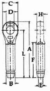
|
S-502 Closed Socket Specifications |
|||||||||||
|---|---|---|---|---|---|---|---|---|---|---|---|
|
Rope Size (in.) |
Weight Each (lbs) |
Before Swage Dimensions |
Max. After Swage Dim. (in.) |
||||||||
|
A |
B |
C |
D |
E |
F |
H |
L |
||||
|
1/4 |
.33 |
4.28 |
.50 |
1.38 |
.76 |
.27 |
2.19 |
.50 |
3.50 |
.46 |
|
|
5/16 |
.75 |
5.42 |
.77 |
1.62 |
.88 |
.34 |
3.25 |
.68 |
4.50 |
.71 |
|
|
3/8 |
.72 |
5.42 |
.78 |
1.62 |
.88 |
.41 |
3.25 |
.68 |
4.50 |
.71 |
|
|
7/16 |
1.42 |
6.88 |
1.01 |
2.00 |
1.07 |
.49 |
4.31 |
.87 |
5.75 |
.91 |
|
|
1/2 |
1.42 |
6.88 |
1.01 |
2.00 |
1.07 |
.55 |
4.31 |
.87 |
5.75 |
.91 |
|
|
9/16 |
2.92 |
8.59 |
1.27 |
2.38 |
1.28 |
.61 |
5.38 |
1.14 |
7.25 |
1.16 |
|
|
5/8 |
2.85 |
8.59 |
1.27 |
2.38 |
1.28 |
.68 |
5.38 |
1.14 |
7.25 |
1.16 |
|
|
3/4 |
5.00 |
10.25 |
1.56 |
2.88 |
1.49 |
.80 |
6.44 |
1.33 |
8.63 |
1.42 |
|
|
7/8 |
6.80 |
11.87 |
1.7Z |
3.12 |
1.73 |
.94 |
7.50 |
1.53 |
10.09 |
1.55 |
|
|
1 |
10.40 |
13.56 |
2.00 |
3.62 |
2.11 |
1.07 |
8.63 |
1.78 |
11.50 |
1.80 |
|
|
1 1/8 |
14.82 |
15.03 |
2.25 |
4.00 |
2.37 |
1.19 |
9.75 |
2.03 |
12.75 |
2.05 |
|
|
1 1/4 |
21.57 |
16.94 |
2.53 |
4.50 |
2.62 |
1.34 |
10.81 |
2.25 |
14.38 |
2.30 |
|
|
1 3/8 |
28.54 |
18.59 |
2.81 |
5.00 |
2.62 |
1.46 |
11.88 |
2.29 |
15.75 |
2.56 |
|
|
1 1/2 |
38.06 |
20.13 |
3.08 |
5.38 |
2.87 |
1.59 |
12.94 |
2.56 |
17.00 |
2.81 |
|
|
1 3/4 |
51.00 |
23.56 |
3.40 |
6.25 |
3.63 |
1.87 |
15.06 |
3.08 |
20.00 |
3.06 |
|
|
2 |
89.25 |
27.13 |
3.94 |
7.25 |
3.88 |
2.12 |
17.06 |
3.31 |
23.00 |
3.56 |
|
- Alloy Slings
- Carbon Steel
Working Load Limits of 100 Grade Chain Slings
|
Single chain slings type S & C |
Double chain slings - type D |
|||
|---|---|---|---|---|
|
Chain Size |
On Straight Lift (90°) |
60° |
45° |
30° |
|
9/32 |
4,300 bs. |
7,400 lbs. |
6,100 bs. |
4,300 lbs. |
|
3/8 |
8,800 lbs. |
15,200 lbs. |
12,400 lbs. |
8,800 lbs. |
|
1/2 |
15,000 bs. |
26,000 lbs. |
21,200 bs. |
15,000lbs. |
|
5/8 |
22,600 lbs. |
39,100 lbs. |
32,000 lbs. |
22,600 lbs. |
|
3/4 |
35,300 bs. |
61,100 lbs. |
49,900 bs. |
35,300 lbs. |
|
7/8 |
42,700 lbs. |
74,000 lbs. |
60,400 lbs. |
42,700 lbs. |
Working load limit in pounds when used with branches at angle of inclination to horizontal load as shown.
|
Triple chain slings - type T |
|||
|---|---|---|---|
|
Chain Size |
60° |
45° |
30° |
|
9/32 |
11,200 bs. |
9,100 lbs. |
6 400lbs. |
|
3/8 |
22,900 lbs. |
18,700 lbs. |
13,200 lbs. |
|
1/2 |
39,000 bs. |
31,800 lbs. |
22,500 lbs. |
|
5/8 |
58,700 lbs. |
47,900 lbs. |
33,900 lbs. |
|
3/4 |
91,700 bs. |
74,900 lbs. |
53,000 lbs. |
|
7/8 |
110,900 lbs. |
90,600 lbs. |
64,000 lbs. |
Working load limit in pounds when used with branches at angle of inclination to horizontal load as shown.
USE OF CHAIN UNDER HEAT CONDITIONS
When the chain itself is heated to temperatures shown below, the working load limits should be reduced as indicated.
|
Temperature of |
Reduction in Working |
Permanent Reduction in |
|---|---|---|
|
500° F. |
none |
none |
|
600° F. |
10% |
none |
|
700° F. |
20% |
none |
|
800° F. |
30% |
none |
|
900° F. |
40% |
10% |
|
*1000° F. |
50% |
15% |
|
1 When chain is at room temperature shown in first column. |
||
Welded Chain
TRANSPORT CHAIN (GRADE 70)
|
Trade Size |
Size Material |
Working* Load |
Nominal Inside |
Nominal Inside |
Maximum Length |
Weight per |
|---|---|---|---|---|---|---|
|
1/4 |
9/32 |
3,150 |
.76 |
.40 |
87 |
76 |
|
5/16 |
11/32 |
4,700 |
.98 |
.46 |
102 |
113 |
|
3/8 |
13/32 |
6,600 |
1.14 |
.54 |
119 |
162 |
|
7/16 |
15/32 |
8,750 |
1.29 |
.62 |
134 |
212 |
|
1/2 |
17/32 |
11,300 |
1.43 |
.72 |
149 |
270 |
*Working load limit must not be exceeded.
Not to be used for overhead lifting.
Boomer chains or binder chains available on request.
HIGH TEST CHAIN (GRADE 43)
|
Trade Size |
Size Material |
Working* Load |
Nominal Inside |
Nominal Inside |
Maximum Length |
Weight per |
|---|---|---|---|---|---|---|
|
1/4 |
9/32 |
2,600 |
.82 |
.39 |
86 |
75 |
|
5/16 |
11/32 |
3,900 |
1.01 |
.48 |
105 |
111 |
|
3/8 |
13/32 |
5,400 |
1.15 |
.56 |
121 |
157 |
|
7/16 |
15/32 |
7,200 |
1.29 |
.65 |
135 |
213 |
|
1/2 |
17/32 |
9,200 |
1.43 |
.75 |
150 |
274 |
|
5/8 |
21/32 |
13,000 |
1.79 |
.90 |
186 |
409 |
|
3/4 |
25/32 |
20,200 |
1.96 |
1.06 |
205 |
603 |
|
7/8 |
29/32 |
24,500 |
2.25 |
1.14 |
235 |
735 |
|
1 |
1/32 |
26,500 |
2.66 |
1.34 |
277 |
975 |
*Working load limit must not be exceeded.
Not to be used for overhead lifting.
HIGH TEST BOOM CHAINS OR BINDER CHAINS
* Working load limit must not be exceeded. Not to be used for overhead lifting.
|
Size X Length |
Working* Load Limit |
Approx. Weight |
|---|---|---|
|
1/4" X 20' |
2,600 |
16 |
|
5/16" X 20' |
3,900 |
22 |
|
3/8" X 20' |
5,400 |
32 |
|
7/16" X 20' |
7,200 |
44 |
|
1/2" X 20' |
9,200 |
54 |
|
5/8" X 20' |
13,000 |
86 |
PROOF COIL CHAIN (GRADE 30)
A general utility chain for such uses as log chain, cargo lashing chain, pipe tine hanging chain, tailgate, guard rail, tow and switch chain.
Finish: self-colored, bright zinc and hot galvanized.
|
Trade Size |
Size Material |
Working* Load |
Nominal Inside |
Nominal Inside |
Maximum Length |
Weight per |
|---|---|---|---|---|---|---|
|
3/16 |
7/32 |
800 |
.95 |
.40 |
99 |
40 |
|
1/4 |
9/32 |
1,300 |
1.00 |
.50 |
104 |
71 |
|
5/16 |
11/32 |
1,900 |
1.10 |
.50 |
114 |
107 |
|
3/8 |
13/32 |
2,650 |
1.23 |
.62 |
128 |
158 |
|
7/18 |
15/32 |
3,700 |
1.38 |
.75 |
142 |
213 |
|
1/2 |
17/32 |
4,500 |
1.50 |
.81 |
156 |
278 |
|
5/8 |
21/32 |
6,900 |
1.87 |
1.00 |
194 |
410 |
|
3/4 |
25/32 |
10,600 |
2.12 |
1.12 |
220 |
580 |
|
7/8 |
29/32 |
12,800 |
2.50 |
1.37 |
260 |
811 |
|
1 |
1 1/32 |
17,900 |
2.75 |
1.50 |
286 |
1045 |
- Type 1 & 2
- Type 3 & 4
- Type 5
Types 1 & 2
TYPE 1

Heavy Duty |
|||||
|
TYPE 1 |
TYPE 2* |
Web Width |
RATED CAPACITIES IN LBS. |
||
|---|---|---|---|---|---|
|
VERTICAL |
CHOKER |
BASKET |
|||
|
ONE PLY |
|||||
|
TC1-902 |
TT1-902 |
2 |
3,200 |
2,500 |
6,400 |
|
TC1-903 |
TT1-903 |
3 |
4,800 |
3,800 |
9,600 |
|
TC1-904 |
TT1-904 |
4 |
6,400 |
5,000 |
12,800 |
|
TC1-906 |
TT1-906 |
6 |
9,600 |
7,700 |
19,200 |
|
TC1-908 |
TT1-908 |
8 |
12,800 |
10,200 |
25,600 |
|
TC1-910 |
TT1-910 |
10 |
16,000 |
12,800 |
32,000 |
|
TC1-912 |
TT1-912 |
12 |
19,200 |
15,400 |
38,400 |
|
TWO PLY |
|||||
|
TC2-902 |
TT2-902 |
2 |
6,400 |
5,000 |
12,800 |
|
TC2-903 |
TT2-903 |
3 |
8,600 |
6,900 |
17,200 |
|
TC2-904 |
TT2-904 |
4 |
11,500 |
9,200 |
23,000 |
|
TC2-906 |
TT2-906 |
6 |
16,300 |
13,000 |
32,600 |
|
TC2-908 |
TT2-908 |
8 |
19,200 |
15,000 |
38,400 |
|
TC2-910 |
TT2-910 |
10 |
22,400 |
17,400 |
44,800 |
|
TC2-912 |
TT2-912 |
12 |
26,900 |
21,000 |
53,800 |
Three and four ply hardware slings are available upon request.
* Type 2 cannot be used in a choker hitch.
TYPE 2

Light Duty |
|||||
|
TYPE 1 |
TYPE 2* |
Web Width |
RATED CAPACITIES IN LBS. |
||
|---|---|---|---|---|---|
|
VERTICAL |
CHOKER |
BASKET |
|||
|
ONE PLY |
|||||
|
TC1-702 |
TT 1-702 |
2 |
2,400 |
1,900 |
4,800 |
|
TC1-703 |
TT 1-703 |
3 |
3,600 |
2,900 |
7,200 |
|
TC 1-704 |
TT1-704 |
4 |
4,800 |
3,800 |
9,600 |
|
TC1-706 |
TT 1-706 |
6 |
7,200 |
5,800 |
14,400 |
|
TWO PLY |
|||||
|
TC2-702 |
TT2-702 |
2 |
4,800 |
3,800 |
9,600 |
|
TC2-703 |
TT2-703 |
3 |
6,500 |
5,200 |
13,000 |
|
TC2-704 |
TT 2-704 |
4 |
8,600 |
6,900 |
17,200 |
|
TC2-706 |
TT2-706 |
6 |
12,600 |
10,100 |
25,200 |
* Type 2 cannot be used in a choker hitch.
Types 3 & 4
TYPE 3

TYPE 4

Heavy Duty |
||||||
|
TYPE 3 (FLAT EYE) & |
Web Width |
RATED CAPACITIES IN LBS. |
Eye Length |
|||
|---|---|---|---|---|---|---|
|
VERTICAL |
CHOKER |
BASKET |
||||
|
ONE PLY |
||||||
|
EE1-901 |
1 |
1,600 |
1,250 |
3,200 |
9 |
|
|
EE1-902 |
2 |
3,200 |
2,500 |
6,400 |
9 |
|
|
EE1-903 |
3 |
4,800 |
3,800 |
9,600 |
12 |
|
|
EE1-904 |
4 |
6,400 |
5,000 |
12,800 |
12 |
|
|
EE1-906 |
6 |
9,600 |
7,700 |
19,200 |
18 |
|
|
EE1-908 |
8 |
12,800 |
10,200 |
25,600 |
24 |
|
|
EE1-910 |
10 |
16,000 |
12,800 |
32,000 |
30 |
|
|
EE1-912 |
12 |
19,200 |
15,400 |
38,400 |
30 |
|
|
TWO PLY |
||||||
|
EE2-901 |
1 |
3,200 |
2,500 |
6,400 |
9 |
|
|
EE2-902 |
2 |
6,400 |
5,000 |
12,800 |
9 |
|
|
EE2-903 |
3 |
8,600 |
6,900 |
17,200 |
12 |
|
|
EE2-904 |
4 |
11,500 |
9,200 |
23,000 |
12 |
|
|
EE2-906 |
6 |
16,300 |
13,000 |
32,600 |
18 |
|
|
EE2-908 |
8 |
19,200 |
15,400 |
38,400 |
24 |
|
|
EE2-910 |
10 |
22,400 |
17,900 |
44,800 |
30 |
|
|
EE2-912 |
12 |
26,900 |
21,500 |
53,800 |
30 |
|
|
THREE PLY |
||||||
|
EE3-901 |
1 |
4,100 |
3,300 |
8,200 |
12 |
|
|
EE3-902 |
2 |
8,300 |
6,600 |
16,600 |
12 |
|
|
EE3-903 |
3 |
12,500 |
10,000 |
25,000 |
18 |
|
|
EE3-904 |
4 |
16,000 |
12,800 |
32,000 |
18 |
|
|
EE3-906 |
6 |
23,000 |
18,400 |
46,000 |
24 |
|
|
EE3-908 |
8 |
30,700 |
24,500 |
61,400 |
30 |
|
|
EE3-910 |
10 |
36,800 |
29,400 |
73,600 |
36 |
|
|
EE3-912 |
12 |
44,000 |
35,200 |
88,000 |
36 |
|
|
FOUR PLY |
||||||
|
EE4-901 |
1 |
5,000 |
4,000 |
10,000 |
12 |
|
|
EE4-902 |
2 |
10,000 |
8,000 |
20,000 |
12 |
|
|
EE4-903 |
3 |
14,900 |
11,900 |
29,800 |
18 |
|
|
EE4-904 |
4 |
19,800 |
15,800 |
39,600 |
18 |
|
|
EE4-906 |
6 |
29,800 |
23,800 |
59,600 |
24 |
|
|
EE4-908 |
8 |
39,700 |
31,700 |
79,400 |
30 |
|
|
EE4-910 |
10 |
49,600 |
39,600 |
99,200 |
36 |
|
|
EE4-912 |
12 |
59.500 |
47600 |
119,000 |
36 |
|
Type 5
- Type 5 endless slings are not tapered unless specified.
- Heavy duty slings also available with reinforced edge webbing.
TYPE 5

|
Type 5 (EN) |
Web Width (in.) |
Rated Capacities in Pounds |
||||
|---|---|---|---|---|---|---|
|
Vertical |
Choker |
Basket |
||||
|
ONE PLY |
||||||
|
EN1-901 |
1 |
3,200 |
2,500 |
6,400 |
||
|
EN1-902 |
2 |
6,400 |
5,000 |
12,800 |
||
|
EN1-903 |
3 |
8,600 |
6,900 |
17,200 |
||
|
EN1-904 |
4 |
11,500 |
9,200 |
23,000 |
||
|
EN1-906 |
6 |
16,300 |
13,000 |
32,600 |
||
|
EN1-908 |
8 |
19,200 |
15,400 |
38,400 |
||
|
EN1-910 |
10 |
22,400 |
17,900 |
44,800 |
||
|
EN1-912 |
12 |
26,900 |
21,500 |
53,800 |
||
|
TWO PLY |
||||||
|
EN2-901 |
1 |
6,200 |
4,900 |
12,400 |
||
|
EN2-902 |
2 |
12,200 |
9,800 |
24,400 |
||
|
EN2-903 |
3 |
16,300 |
13,000 |
32,600 |
||
|
EN2-904 |
4 |
20,700 |
16,500 |
41,400 |
||
|
EN2-906 |
6 |
28,600 |
23,000 |
57,200 |
||
|
EN2-908 |
8 |
30,700 |
24,500 |
61,400 |
||
|
EN2-91O |
10 |
33,600 |
26,800 |
67,200 |
||
|
EN2-912 |
12 |
37,600 |
30,000 |
75,200 |
||
|
THREE PLY |
||||||
|
EN3-901 |
1 |
8,000 |
6,400 |
16,000 |
||
|
EN3-902 |
2 |
16,000 |
12,800 |
32,000 |
||
|
EN3-903 |
3 |
21,500 |
17,200 |
43,000 |
||
|
EN3-904 |
4 |
28,700 |
23,000 |
57,400 |
||
|
EN3-906 |
6 |
40,700 |
32,500 |
81,400 |
||
|
EN3-908 |
8 |
46,000 |
36,800 |
92,000 |
||
|
EN3-910 |
10 |
51,500 |
41,200 |
103,000 |
||
|
EN3-912 |
12 |
59,200 |
47,300 |
118,400 |
||
|
FOUR PLY |
||||||
|
EN4-901 |
1 |
10,000 |
8,000 |
20,000 |
||
|
EN4-902 |
2 |
19,800 |
15,800 |
39,600 |
||
|
EN4-903 |
3 |
26,700 |
21,300 |
53,400 |
||
|
EN4-904 |
4 |
35,600 |
28,400 |
71,200 |
||
|
EN4-906 |
6 |
50,500 |
40,400 |
101,000 |
||
|
EN4-908 |
8 |
57,600 |
46,000 |
115,200 |
||
|
EN4-910 |
10 |
67,200 |
53,700 |
134,400 |
||
|
EN4-912 |
12 |
80,700 |
64,500 |
161,400 |
||
|
Type 5 (EN) |
Web Width (in.) |
Rated Capacities in Pounds |
||||
|---|---|---|---|---|---|---|
|
Vertical |
Choker |
Basket |
||||
|
ONE PLY |
||||||
|
EN1-901 |
1 |
3,200 |
2,500 |
6,400 |
||
|
EN1-902 |
2 |
6,400 |
5,000 |
12,800 |
||
|
EN1-903 |
3 |
8,600 |
6,900 |
17,200 |
||
|
EN1-904 |
4 |
11,500 |
9,200 |
23,000 |
||
|
EN1-906 |
6 |
16,300 |
13,000 |
32,600 |
||
|
EN1-908 |
8 |
19,200 |
15,400 |
38,400 |
||
|
EN1-910 |
10 |
22,400 |
17,900 |
44,800 |
||
|
EN1-912 |
12 |
26,900 |
21,500 |
53,800 |
||
|
TWO PLY |
||||||
|
EN2-901 |
1 |
6,200 |
4,900 |
12,400 |
||
|
EN2-902 |
2 |
12,200 |
9,800 |
24,400 |
||
|
EN2-903 |
3 |
16,300 |
13,000 |
32,600 |
||
|
EN2-904 |
4 |
20,700 |
16,500 |
41,400 |
||
|
EN2-906 |
6 |
28,600 |
23,000 |
57,200 |
||
|
EN2-908 |
8 |
30,700 |
24,500 |
61,400 |
||
|
EN2-91O |
10 |
33,600 |
26,800 |
67,200 |
||
|
EN2-912 |
12 |
37,600 |
30,000 |
75,200 |
||
|
THREE PLY |
||||||
|
EN3-901 |
1 |
8,000 |
6,400 |
16,000 |
||
|
EN3-902 |
2 |
16,000 |
12,800 |
32,000 |
||
|
EN3-903 |
3 |
21,500 |
17,200 |
43,000 |
||
|
EN3-904 |
4 |
28,700 |
23,000 |
57,400 |
||
|
EN3-906 |
6 |
40,700 |
32,500 |
81,400 |
||
|
EN3-908 |
8 |
46,000 |
36,800 |
92,000 |
||
|
EN3-910 |
10 |
51,500 |
41,200 |
103,000 |
||
|
EN3-912 |
12 |
59,200 |
47,300 |
118,400 |
||
|
FOUR PLY |
||||||
|
EN4-901 |
1 |
10,000 |
8,000 |
20,000 |
||
|
EN4-902 |
2 |
19,800 |
15,800 |
39,600 |
||
|
EN4-903 |
3 |
26,700 |
21,300 |
53,400 |
||
|
EN4-904 |
4 |
35,600 |
28,400 |
71,200 |
||
|
EN4-906 |
6 |
50,500 |
40,400 |
101,000 |
||
|
EN4-908 |
8 |
57,600 |
46,000 |
115,200 |
||
|
EN4-910 |
10 |
67,200 |
53,700 |
134,400 |
||
|
EN4-912 |
12 |
80,700 |
64,500 |
161,400 |
||
Polyester Round Slings
- A polyester roundsling shall be removed from service if any of the following is visible:
- If sling identification tag is missing or not readable.
- Melting, charring or weld spatter of any part of the web sling.
- Holes, tears, cuts, embedded particles, abrasive wear or snags that expose the core fibers of the polyester roundsling.
- Broke or worn stitching in the cover which exposes the core fibers.
- Fittings when damaged, stretched, or distorted in any way.
- Polyester roundslings that are knotted.
- Acid or alkali burns of the sling.
- Any conditions which cause doubt as to the strength of the polyester roundsling.
ENDLESS ROUNDSLINGS
|
LIFT CAPACITIES ACCORDING TO TYPE (COLOR) AND HITCH USED |
||||||
|---|---|---|---|---|---|---|
|
Code |
Color |
Rated Capacities in Pounds |
Min. Length (ft.) |
Approx. Weight (lbs/ft) |
||
|
Vertical |
Choker |
Basket |
||||
|
SWG30 |
|
2,650 |
2,210 |
5,300 |
1.5 |
0.20 |
|
SWG60 |
|
5,300 |
4,240 |
10,600 |
1.5 |
0.30 |
|
SWG90 |
|
8,400 |
6,720 |
16,800 |
2 |
0.50 |
|
SWG120 |
|
10,600 |
8,500 |
21,200 |
2 |
0.60 |
|
SWG150 |
|
13,200 |
10,560 |
26,400 |
3 |
0.80 |
|
SWG180 |
|
16,800 |
13,440 |
33,600 |
3 |
0.90 |
|
SWG240 |
|
21,200 |
17,000 |
42,400 |
3 |
1.30 |
|
SWG300 |
|
25,000 |
20,000 |
50,000 |
3 |
1.50 |
|
SWG360 |
|
31,700 |
25,300 |
63,400 |
3 |
1.70 |
|
SWG500 |
|
40,000 |
32,000 |
80,000 |
4 |
2.20 |
|
SWG600 |
|
52,900 |
42,300 |
105,800 |
6 |
2.80 |
|
SWG800 |
|
66,100 |
52,880 |
132,200 |
6 |
3.40 |
|
SWG1000 |
|
90,000 |
72,000 |
180,000 |
6 |
4.30 |
EYE AND EYE ROUNDSLINGS
|
LIFT CAPACITIES ACCORDING TO TYPE (COLOR) AND HITCH USED |
|||||||
|---|---|---|---|---|---|---|---|
|
Code |
Color |
Rated Capacities in Pounds |
Min. Length |
Approx. |
Standard Eye |
||
|
Vertical |
Choker |
Basket |
|||||
|
SWG30 |
|
2,650 |
2,210 |
5,300 |
3 |
0.25 |
9 |
|
SWG60 |
|
5,300 |
4,240 |
10,600 |
3 |
0.36 |
9 |
|
SWG90 |
|
8,400 |
6,720 |
16,800 |
4 |
0.55 |
12 |
|
SWG120 |
|
10,600 |
8,500 |
21,200 |
4 |
0.65 |
12 |
|
SWG150 |
|
13,200 |
10,560 |
26,400 |
4 |
0.84 |
12 |
|
SWG180 |
|
16,800 |
13,440 |
33,600 |
6 |
0.96 | 18 |
|
SWG240 |
|
21,200 |
17,000 |
42,400 |
6 |
1.50 |
18 |
|
SWG300 |
|
25,000 |
20,000 |
50,000 |
6 |
1.70 |
18 |
|
SWG360 |
|
31,700 |
25,300 |
63,400 |
6 |
2.00 |
18 |
|
SWG500 |
|
40,000 |
32,000 |
80,000 |
8 |
2.40 |
24 |
|
SWG600 |
|
52,900 |
42,300 |
105,800 |
8 |
3.10 |
24 |
|
SWG800 |
|
66,100 |
52,880 |
132,200 |
10 |
3.70 |
30 |
|
SWG1000 |
|
90,000 |
72,000 |
180,000 |
10 |
4.60 |
30 |
- HMPE
- General Purpose
Plasma® 12 Strand
|
Specific gravity: |
0.98* |
|
Melting point: |
284° F (140° C) |
|
Critical temp.: |
150° F (65° C) |
|
Coefficient of friction: |
0.09 -.12* |
|
Elongation at break: |
4% - 5% |
|
Fiber water absorption: |
0% |
|
UV resistance: |
moderate |
|
Wet abrasion: |
superior |
|
Dry abrasion: |
superior |
|
* value based on data supplied by the fiber manufacturer for new, dry fiber |
|
• Tensile Strengths are determined in accordance with Cordage Institute 1500.2. Test Methods for Fiber Rope. Minimum Tensile Strength (MTS) published assumes spliced eye tenninations at each end of the rope. Weights actually calculated at linear density under state preloaded (200d’J plus 4%. Diameter and circumference size published is nominal and reflects rope size after loading (10 cycles) to 50% ofMTS. See reverse side for application and safety information .
• Plasma is a Trademark of Cortland.
Plasma® 12 strand is the highest strength synthetic rope available. Plasma® 12 strand is manufactured from High Modulus Polyethylene (HMPE) that has been enhanced by Cortland’s patented recrystallization process. This process is especially effective in medium to large diameter ropes where strengths are over 50% higher and creep is significantly less than that of standard Spectra® 12 strand.
Plasma® 12 strand is delivered standard with a polyurethane finish and is easily spliced using a simple lockstitch type splice, 4-3-2 or 5-4-3 Tuck Splice. Its soft, torque free braided construction provides easy handling.
|
Nominal Diameter |
Size (circ in.) |
Approximate Weight |
Min Tensile Strength |
|||
|---|---|---|---|---|---|---|
|
Inch |
MM |
Lbs/100 ft. |
Kg/100 m |
Lbs |
Te (tonnes) |
|
|
0.04 |
1 |
0.12 |
0.05 |
0.10 |
270 |
0.10 |
|
0.05 |
1.25 |
0.15 |
0.07 |
0.10 |
390 |
0.20 |
|
0.06 |
1.5 |
0.18 |
0.10 |
0.10 |
475 |
0.20 |
|
0.07 |
1.75 |
0.21 |
0.14 |
0.20 |
750 |
0.30 |
|
0.1 |
2.5 |
0.30 |
0.27 |
0.40 |
1,400 |
0.60 |
|
1/8 |
3 |
3/8 |
0.54 |
0.80 |
2,800 |
1.30 |
|
3/16 |
5 |
9/16 |
1.12 |
1.70 |
5,500 |
2.50 |
|
1/4 |
6 |
3/4 |
1.60 |
2.40 |
8,000 |
3.60 |
|
5/16 |
8 |
15/16 |
2.50 |
3.70 |
11,700 |
5.30 |
|
3/8 |
9 |
1 1/8 |
3.70 |
5.50 |
17 500 |
7.90 |
|
ABS and DNV Type Approved Sizes |
||||||
|
7/16 |
11 |
1 1/4 |
4.20 |
6.30 |
21,000 |
9.50 |
|
1/2 |
12 |
1 1/2 |
6.40 |
9.50 |
31,300 |
14.2 |
|
9/16 |
14 |
1 3/4 |
7.90 |
11.8 |
37,900 |
17.2 |
|
5/8 |
16 |
2 |
10.6 |
15.8 |
51,400 |
23.3 |
|
3/4 |
18 |
2 1/4 |
13.3 |
19.8 |
68,500 |
31.1 |
|
13/16 |
20 |
2 1/2 |
15.9 |
23.7 |
74,000 |
33.6 |
|
7/8 |
22 |
2 3/4 |
19.6 |
29.2 |
92,600 |
42.0 |
|
1 |
24 |
3 |
23.4 |
34.8 |
110,000 |
49.9 |
|
1 1/16 |
26 |
3 1/4 |
27.5 |
40.9 |
129,200 |
58.6 |
|
1 1/8 |
28 |
3 1/2 |
31.9 |
47.5 |
147,000 |
66.7 |
|
1 1/4 |
30 |
3 3/4 |
36.2 |
53.9 |
165,000 |
74.9 |
|
1 5/16 |
32 |
4 |
41.7 |
62.1 |
196,000 |
88.9 |
|
1 1/2 |
36 |
4 1/2 |
51.7 |
76.9 |
221,000 |
100.3 |
General Purpose
- Diameters are approximate. The reference for rope size is its linear density or weight per unit length.
- Linear Density is considered standard. Tolerances are± 10% for diameters below B mm inclusive;± 8% for diameters 10-14 mm inclusive;± 5% for 16 mm diameter and larger.
- Minimum Breaking Strength (MBS) values in individual rope standards are based on data from a number of rope manufacturers and the result of computation by regression analysis.
- The MBS values are based on ropes tested with Eye Splices, making the values approximately 10 % lower than ropes tested without splices.
- Working Load Limit (WLL) is determined by dividing the new rope MBS by a selected Design Factor.
|
Nominal Size |
Manila |
Nylon |
Polypropylene |
|||||||
|---|---|---|---|---|---|---|---|---|---|---|
|
Diameter |
Circumference |
Linear Density
|
MBS
|
WLL (Lbs)
|
Linear Density
|
MBS
|
WLL (Lbs)
|
Linear Density
|
MBS
|
WLL (Lbs)
|
|
3/16 |
5/8 |
1.37 |
405 |
33.8 |
0.89 |
880 |
73 |
0.65 |
730 |
61 |
|
1/4 |
3/4 |
1.82 |
540 |
45 |
1.57 |
1,490 |
124 |
1.15 |
1,260 |
105 |
|
5/16 |
1 |
2.64 |
900 |
75 |
2.45 |
2,300 |
192 |
1.80 |
1,915 |
160 |
|
3/8 |
1 1/8 |
3.79 |
1,215 |
101 |
3.55 |
3,240 |
270 |
2.60 |
2,720 |
227 |
|
7/16 |
1 1/4 |
4.87 |
1,575 |
131 |
4.80 |
4,320 |
360 |
3.50 |
3,525 |
294 |
|
1/2 |
1 1/2 |
6.96 |
2,385 |
199 |
6.30 |
5,670 |
473 |
4.60 |
4,235 |
353 |
|
9/16 |
1 3/4 |
9.63 |
3,105 |
259 |
8.00 |
7,200 |
600 |
5.90 |
5,140 |
428 |
|
5/8 |
2 |
12.7 |
3,960 |
330 |
9.90 |
8,910 |
743 |
7.20 |
6,250 |
521 |
|
3/4 |
2 1/4 |
15.9 |
4,860 |
405 |
14.3 |
12,800 |
1,070 |
10.4 |
8,570 |
714 |
|
7/8 |
2 3/4 |
21.4 |
6,930 |
578 |
19.5 |
17,300 |
1,440 |
14.2 |
11,600 |
967 |
|
1 |
3 |
25.7 |
8,100 |
675 |
25.3 |
22,200 |
1,850 |
18.0 |
14,400 |
1,200 |
|
1 1/16 |
3 1/4 |
29.8 |
9,450 |
788 |
28.7 |
25,200 |
2,100 |
20.4 |
16,100 |
1,342 |
|
1 1/8 |
3 1/2 |
34.3 |
10,800 |
900 |
32.2 |
28,300 |
2,360 |
22.8 |
17,900 |
1,492 |
|
1 1/4 |
3 3/4 |
39.7 |
12,150 |
1,013 |
39.7 |
34,800 |
2,900 |
27.6 |
21,700 |
1,808 |
|
1 5/16 |
4 |
45.6 |
13,500 |
1,125 |
43.7 |
38,300 |
3,190 |
30.4 |
23,700 |
1,975 |
|
1 1/2 |
4 1/2 |
57.0 |
16,650 |
1,388 |
57.0 |
48,600 |
4,050 |
39.4 |
30,600 |
2,550 |
|
1 5/8 |
5 |
71.1 |
20,250 |
1,688 |
67.3 |
57,400 |
4,780 |
46.0 |
35,800 |
2,983 |
|
1 3/4 |
5 1/2 |
85.0 |
23,850 |
1,988 |
78.0 |
66,100 |
5,510 |
53.0 |
41,300 |
3,442 |
|
2 |
6 |
102 |
27,900 |
2,325 |
100 |
84,600 |
7,050 |
69.0 |
52,400 |
4,367 |
|
2 1/8 |
6 1/2 |
120 |
32,400 |
2,700 |
113 |
95,400 |
7,950 |
78.0 |
59,000 |
4,917 |
|
2 1/4 |
7 |
139 |
36,900 |
3,075 |
127 |
107,000 |
8,920 |
88.0 |
66,500 |
5,542 |
|
2 1/2 |
7 1/2 |
164 |
42,300 |
3,525 |
157 |
131,000 |
10,900 |
107 |
80,600 |
6,717 |
|
2 5/8 |
8 |
182 |
46,800 |
3,900 |
173 |
144,000 |
12,000 |
120 |
90,200 |
7,517 |
|
2 3/4 |
8 1/2 |
215 |
54,900 |
4,575 |
208 |
171,000 |
14,300 |
141 |
105,800 |
8,817 |
|
3 |
9 |
230 |
57,500 |
4,792 |
226 |
185,000 |
15,400 |
153 |
114,900 |
9,575 |
|
3 1/4 |
10 |
284 |
69,500 |
5,792 |
275 |
224,000 |
18,700 |
186 |
136,000 |
11,333 |
|
3 1/2 |
11 |
349 |
81,900 |
6,825 |
329 |
267,000 |
22,300 |
223 |
161,300 |
13,442 |
|
4 |
12 |
414 |
94,500 |
7,875 |
400 |
324,000 |
27,000 |
272 |
192,500 |
16,042 |
|
4 1/4 |
13 |
- |
- |
- |
460 |
369,000 |
30,800 |
315 |
221,800 |
18,483 |
|
4 1/2 |
14 |
- |
- |
- |
525 |
419,000 |
34,900 |
360 |
250,000 |
20,833 |
|
5 |
15 |
- |
- |
- |
610 |
481,000 |
40,100 |
420 |
287,300 |
23,942 |
|
5 5/16 |
16 |
- |
- |
- |
685 |
533,000 |
44,400 |
474 |
321,600 |
26,800 |
|
5 5/8 |
17 |
- |
- |
- |
767 |
590,000 |
49,200 |
531 |
357,800 |
29,817 |
|
6 |
18 |
- |
- |
- |
870 |
661,000 |
55,100 |
603 |
401,200 |
33,133 |
- SPA Shackles
- Alloy BTA Shackles
- Sling Shackles
- Drop Forge Malleable Clips
- Double Saddle Clips
- Thimbles
- Turnbuckles
Screw Pin Anchor Shackles
GALVANIZED CARBON STEEL
|
Nominal Size (in.) |
Working Load Limit (t)* |
Weight Each (lbs) |
Dimensions (in.) |
Tolerance |
|||||||||||
|---|---|---|---|---|---|---|---|---|---|---|---|---|---|---|---|
|
A |
B |
C |
D |
E |
F |
G |
H |
L |
M |
P |
C |
A |
|||
|
3/16 |
1/3 |
.06 |
.38 |
.25 |
.88 |
.19 |
.60 |
.56 |
.98 |
1.47 |
.16 |
1.12 |
.19 |
.06 |
.06 |
|
1/4 |
1/2 |
.10 |
.47 |
.31 |
1.13 |
.25 |
.78 |
.61 |
1.28 |
1.84 |
.19 |
1.38 |
.25 |
.06 |
.06 |
|
5/16 |
3/4 |
.19 |
.53 |
.38 |
1.22 |
.31 |
.84 |
.75 |
1.47 |
12.09 |
.22 |
1.66 |
.31 |
.06 |
.06 |
|
3/8 |
1 |
.31 |
.66 |
.44 |
1.44 |
.38 |
1.03 |
.91 |
1.78 |
2.49 |
.25 |
2.03 |
.38 |
.13 |
.06 |
|
7/16 |
1 1/2 |
.38 |
.75 |
.50 |
1.69 |
.44 |
1.16 |
1.06 |
2.03 |
2.91 |
.31 |
2.38 |
.44 |
.13 |
.06 |
|
1/2 |
2 |
.72 |
.81 |
.63 |
1.88 |
.50 |
1.31 |
1.19 |
2.31 |
3.28 |
.38 |
2.69 |
.15 |
.13 |
.06 |
|
5/8 |
3 1/4 |
1.37 |
1.06 |
.75 |
2.38 |
.63 |
1.69 |
1.50 |
2.94 |
4.19 |
.44 |
3.44 |
.69 |
.13 |
.06 |
|
3/4 |
4 3/4 |
2.35 |
1.25 |
.88 |
2.81 |
.75 |
2.00 |
1.81 |
3.50 |
4.97 |
.50 |
3.97 |
.81 |
.25 |
.06 |
|
7/8 |
6 1/2 |
3.62 |
1.44 |
1.00 |
3.31 |
.88 |
2.28 |
2.09 |
4.03 |
5.83 |
.50 |
4.50 |
.97 |
.25 |
.06 |
|
1 |
8 1/2 |
5.03 |
1.69 |
1.13 |
3.75 |
1.00 |
2.69 |
2.38 |
4.69 |
6.56 |
.56 |
5.07 |
1.06 |
.25 |
.06 |
|
1 1/8 |
9 1/2 |
7.41 |
1.81 |
1.25 |
4.25 |
1.16 |
2.91 |
2.69 |
5.16 |
7.47 |
.63 |
5.59 |
1.25 |
.25 |
.06 |
|
1 1/4 |
12 |
9.50 |
2.03 |
1.38 |
4.69 |
1.29 |
3.25 |
3.00 |
5.75 |
8.25 |
.69 |
6.16 |
1.38 |
.25 |
.06 |
|
1 3/8 |
13 1/2 |
13.53 |
2.25 |
1.50 |
5.25 |
1.42 |
3.63 |
3.31 |
6.38 |
9.16 |
.75 |
6.84 |
1.50 |
.25 |
.13 |
|
1 1/2 |
17 |
17.20 |
2.38 |
1.63 |
5.75 |
1.54 |
3.88 |
3.63 |
6.88 |
10.00 |
.81 |
1.62 |
.25 |
.13 |
|
|
1 3/4 |
25 |
27.78 |
2.88 |
2.00 |
7.00 |
1.84 |
4.19 |
8.86 |
U |
12.34 |
1.00 |
9.08 |
2.25 |
2.25 |
.13 |
|
2 |
35 |
45.00 |
3.25 |
2.25 |
7.75 |
2.08 |
5.75 |
4.81 |
9.97 |
13.68 |
1.22 |
10.34 |
2.40 |
.25 |
.13 |
|
2 1/2 |
55 |
85.75 |
4.13 |
2.75 |
10.50 |
2.71 |
7.25 |
5.69 |
12.87 |
17.84 |
1.38 |
13.00 |
3.13 |
.25 |
.25 |
Forged steel with Carbon or Alloy pins – quenched & tempered.
* Maximum Proof Load is 2 times the Working Load Limit (metric tons) and 2.2 times the Working Load
Limit (short tons).
Minimum Ultimate Strength is 45 times the Working Load Limit (metric tons), and 5 times the Working Load
Limit.
GALVANIZED ALLOY STEEL
|
Nominal Size (in.) |
Working Load Limit (t)* |
Weight Each (lbs) |
Dimensions (in.) |
Tolerance |
|||||||||||
|---|---|---|---|---|---|---|---|---|---|---|---|---|---|---|---|
|
A |
B |
C |
D |
E |
F |
G |
H |
L |
M |
P |
C |
A |
|||
|
3/8 |
2 |
.31 |
.66 |
.44 |
1.44 |
.38 |
1.03 |
.91 |
1.78 |
2.49 |
.25 |
2.03 |
.38 |
.13 |
.06 |
|
7/16 |
2 2/3 |
.38 |
.75 |
.50 |
1.69 |
.44 |
1.16 |
1.06 |
2.03 |
2.91 |
.31 |
2.38 |
.44 |
.13 |
.06 |
|
1/2 |
3 1/3 |
.63 |
.81 |
.63 |
1.88 |
.5 |
1.31 |
1.19 |
2.31 |
3.28 |
.38 |
2.69 |
.50 |
.13 |
.06 |
|
5/8 |
5 |
1.38 |
1.06 |
.75 |
2.38 |
.63 |
1.69 |
1.50 |
2.94 |
4.19 |
.44 |
3.34 |
.69 |
.13 |
.06 |
|
3/4 |
7 |
2.25 |
1.25 |
.88 |
2.81 |
.75 |
2.00 |
1.81 |
3.50 |
4.97 |
.50 |
3.97 |
.81 |
.25 |
.06 |
|
7/8 |
9 1/2 |
3.61 |
1.44 |
1.00 |
3.311 |
.88 |
2.28 |
2.09 |
4.03 |
5.83 |
.50 |
4.50 |
.97 |
.25 |
.06 |
|
1 |
12 1/2 |
5.32 |
1.69 |
1.13 |
3.75 |
1.00 |
2.69 |
2.38 |
4.69 |
6.56 |
.56 |
5.07 |
1.06 |
.25 |
.06 |
|
1 1/8 |
15 |
7.25 |
1.81 |
1.25 |
4.25 |
1.16 |
2.91 |
2.69 |
5.16 |
7.47 |
.63 |
5.59 |
1.25 |
.25 |
.06 |
|
1 1/4 |
18 |
9.88 |
2.03 |
1.38 |
4.69 |
1.29 |
3.25 |
3.00 |
5.75 |
8.25 |
.69 |
6.16 |
1.38 |
.25 |
.06 |
|
1 3/8 |
21 |
13.25 |
2.25 |
1.50 |
5.25 |
1.42 |
3.63 |
3.31 |
6.38 |
9.16 |
.75 |
6.84 |
1.50 |
.25 |
.13 |
Meets or exceeds all requirements of ASME B30.26.
GALVANIZED ALLOY BOLT TYPE
|
Working Load Limit |
Diameter |
Diameter |
Diameter |
Width |
Width |
Length |
Width |
Length |
Length |
Width |
Thickness |
Weight |
|---|---|---|---|---|---|---|---|---|---|---|---|---|
|
Tons |
a |
b |
c |
d |
e |
f |
g |
h |
i |
j |
k |
Lbs |
|
3.3 |
1/2 |
5/8 |
1 11/32 |
17/32 |
7/8 |
2 |
1 9/32 |
3 19/32 |
3 9/32 |
2 1/2 |
17/32 |
0.97 |
|
5 |
5/8 |
3/4 |
1 19/32 |
5/8 |
1 3/32 |
2 17/32 |
1 23/32 |
4 1/2 |
3 29/32 |
3 1/8 |
11/16 |
1.74 |
|
7 |
3/4 |
7/8 |
1 7/8 |
3/4 |
1 1/4 |
3 |
2 |
5 11/32 |
4 17/32 |
3 23/32 |
25/32 |
2.78 |
|
9.5 |
7/8 |
1 |
2 3/32 |
7/8 |
1 7/16 |
3 9/23 |
2 9/32 |
6 5/32 |
5 5/32 |
4 3/16 |
29/32 |
4.14 |
|
12.5 |
1 |
1 1/8 |
2 11/32 |
1 |
1 23/32 |
3 3/4 |
2 11/16 |
6 29/32 |
5 15/16 |
4 7/8 |
1 |
6.13 |
|
15 |
1 1/8 |
1 1/4 |
2 5/8 |
1 1/8 |
1 7/8 |
4 1/4 |
2 15/16 |
7 3/4 |
6 19/32 |
5 3/8 |
1 1/8 |
8.53 |
|
18 |
1 1/4 |
1 3/8 |
2 29/32 |
1 9/32 |
2 |
4 17/32 |
3 9/32 |
8 9/16 |
7 1/32 |
63/32 |
1 1/4 |
11.6 |
|
21 |
1 3/8 |
1 1/2 |
3 5/32 |
1 3/8 |
2 1/4 |
5 1/4 |
3 5/8 |
9 7/16 |
7 25/32 |
6 23/32 |
11/32 |
15.3 |
|
30 |
1 1/2 |
1 5/8 |
3 1/2 |
1 17/32 |
2 11/32 |
5 3/4 |
3 29/32 |
10 5/16 |
8 |
7 3/16 |
3/4 |
19.38 |
|
40 |
1 3/4 |
2 |
4 1/8 |
1 25/32 |
2 29/32 |
7 |
4 15/16 |
12 11/32 |
9 9/32 |
8 29/32 |
15/16 |
33.07 |
|
50 |
2 |
2 1/4 |
4 11/16 |
2 31/32 |
3 9/32 |
7 3/4 |
5 7/16 |
14 3/32 |
10 5/8 |
9 13/16 |
1 3/32 |
45.64 |
|
80 |
2 1/2 |
2 3/4 |
5 3/4 |
2 9/16 |
4 1/8 |
10 1/4 |
7 9/32 |
18 1/4 |
13 |
12 15/16 |
1 5/16 |
90.61 |
|
110 |
3 |
3 1/4 |
6 7/16 |
3 15/16 |
5 |
12 15/16 |
7 1/2 |
21 29/32 |
14 25/32 |
14 |
1 19/32 |
137.13 |
|
140* |
3 3/4 |
3 3/4 |
8 1/2 |
3 17/32 |
5 11/16 |
15 |
9 11/16 |
26 9/32 |
17 5/16 |
16 3/8 |
2 |
242.51 |
|
175* |
4 |
4 1/4 |
9 5/8 |
3 15/16 |
6 17/32 |
15 3/4 |
10 13/16 |
27 5/8 |
19 9/32 |
19 1/8 |
23/8 |
352.74 |
* = round headed bolt | ||||||||||||
GALVANIZED WIDE MOUTH ALLOY TOWING SHACKLES
|
Working Load Limit |
Diameter |
Diameter |
Diameter |
Width |
Width |
Length |
Width |
Length |
Length |
Width |
Thickness |
Weight |
|---|---|---|---|---|---|---|---|---|---|---|---|---|
|
Tons |
a |
b |
c |
d |
e |
f |
g |
h |
i |
j |
k |
Lbs |
|
22 |
1 1/2 |
1 5/8 |
3 1/2 |
1 17/32 |
4 3/16 |
8 1/2 |
6 9/32 |
12 9/16 |
9 3/4 |
9 1/4 |
3/4 |
27.56 |
|
30 |
1 3/4 |
2 |
4 1/8 |
1 25/32 |
5 |
9 3/4 |
6 7/8 |
14 9/16 |
11 11/16 |
10 7/16 |
15/16 |
39.68 |
|
40 |
2 |
2 1/4 |
4 11/16 |
1 31/32 |
5 3/4 |
10 3/4 |
8 5/32 |
16 3/16 |
13 5/16 |
11 1/8 |
1 3/32 |
55.12 |
|
55 |
2 1/2 |
2 3/4 |
5 3/4 |
2 9/16 |
6 1/2 |
12 3/8 |
8 3/8 |
19 3/16 |
15 5/16 |
13 1/2 |
1 5/16 |
105.82 |
|
100 |
3 |
3 1/4 |
6 7/16 |
21 5/16 |
7 1/4 |
13 |
10 |
20 7/8 |
17 |
15 7/8 |
1 19/32 |
154.32 |
Green Pin Sling Shackles
- Material: alloy steel, quenched and tempered
- Proofload test certification Lloyd’s Register of Shipping
- Design factor: 5:1
- Finish: body aluminum painted, pin green paint
- Sling Shackles are supplied including material certificates according to EN10204 (DIN 50 049- 3.1b)
- The Sling Shackles are Ultra-sonic- and Magnetic Particle inspected.
|
Working Load |
Dia Body |
Dia Pin |
Inside Width |
Inside Length |
Width of Bow |
Bearing Surface |
Weight Each (Lbs.) |
|---|---|---|---|---|---|---|---|
|
55 |
2 3/8 |
2 1/4 |
3 3/4 |
9 7/8 |
6 5/16 |
4 |
110 |
|
75 |
2 3/4 |
2 3/4 |
4 1/8 |
11 3/8 |
7 5/16 |
4 3/4 |
148 |
|
125 |
3 3/8 |
3 5/32 |
5 1/8 |
14 3/8 |
8 11/16 |
6 |
243 |
|
150 |
3 3/4 |
3 3/4 |
5 17/32 |
15 3/8 |
9 7/8 |
6 3/4 |
353 |
|
200 |
4 5/16 |
4 1/8 |
5 29/32 |
18 7/8 |
10 7/8 |
8 |
485 |
|
250 |
5 |
4 3/4 |
6 23/32 |
21 1/4 |
11 7/8 |
9 1/2 |
705 |
|
300 |
5 5/16 |
5 5/16 |
7 9/32 |
23 5/8 |
13 3/4 |
10 1/2 |
772 |
|
400 |
6 5/16 |
6 5/16 |
8 11/16 |
22 5/8 |
14 9/16 |
12 5/8 |
1,400 |
|
500 |
6 3/4 |
7 1/8 |
9 7/8 |
26 3/4 |
17 3/4 |
13 3/8 |
1,770 |
|
600 |
7 1/2 |
7 7/8 |
10 7/8 |
29 1/8 |
19 1/4 |
14 5/8 |
2,161 |
|
700 |
7 7/8 |
8 1/2 |
11 13/16 |
29 1/2 |
21 1/4 |
15 3/4 |
2,778 |
|
800 |
8 5/8 |
9 1/8 |
12 3/4 |
33 1/2 |
21 7/8 |
16 9/16 |
3,153 |
|
900 |
9 9/16 |
10 |
13 3/4 |
33 1/2 |
23 |
17 3/8 |
3,638 |
|
1000 |
10 1/4 |
10 5/8 |
15 |
33 5/8 |
24 1/8 |
18 1/8 |
4,674 |
|
1250 |
11 1/4 |
11 7/8 |
16 15/16 |
36 5/8 |
25 5/8 |
20 7/8 |
5,291 |
|
1500 |
11 5/8 |
12 5/8 |
18 1/8 |
37 3/8 |
26 3/4 |
22 |
6,570 |
Drop Forged Clips
|
Size |
Min. Clips |
Torque in Ft. Lbs.* |
Amt. Wire Rope |
Approx. Wt. in Lbs |
Dimensions in Inches |
||||||
|---|---|---|---|---|---|---|---|---|---|---|---|
|
A |
B |
C |
D |
E |
F |
G |
|||||
|
1/8 ** |
2 |
4.5 |
3 1/4 |
.05 |
.19 |
.75 |
.44 |
.44 |
.38 |
.81 |
.94 |
|
3/16 ** |
2 |
7.5 |
3 3/4 |
.10 |
.25 |
.94 |
.56 |
.56 |
.50 |
.94 |
1.19 |
|
1/4 |
2 |
1.5 |
4 3/4 |
.18 |
.31 |
1.06 |
.56 |
.75 |
.63 |
1.19 |
1.50 |
|
5/16 |
2 |
30 |
5 1/4 |
.31 |
.38 |
1.44 |
.75 |
.88 |
.75 |
1.31 |
1.69 |
|
3/8 |
2 |
45 |
6 1/2 |
.46 |
.44 |
1.50 |
.75 |
1.00 |
.88 |
1.56 |
1.94 |
|
7/16 |
2 |
65 |
7 |
.73 |
50 |
1.88 |
1.00 |
1.19 |
1.00 |
1.81 |
2.31 |
|
1/2 |
3 |
65 |
11 1/2 |
73 |
50 |
1.88 |
1 00 |
1.19 |
1.06 |
1.81 |
2.31 |
|
9/16 |
3 |
95 |
12 |
96 |
.56 |
2.38 |
1.25 |
1.31 |
1.13 |
2.06 |
2.50 |
|
5/8 |
3 |
95 |
12 |
1.00 |
56 |
2.38 |
1.25 |
1.31 |
1.25 |
2.06 |
2.50 |
|
3/4 |
4 |
130 |
18 |
1.50 |
.63 |
2.75 |
1.38 |
1.50 |
1.38 |
2.31 |
2.75 |
|
7/8 |
4 |
225 |
19 |
2.44 |
.75 |
3.19 |
1.44 |
1.81 |
1.69 |
2.63 |
3.31 |
|
1 |
5 |
225 |
26 |
2.70 |
.75 |
3.63 |
1.75 |
1.88 |
1.75 |
2.63 |
3.47 |
|
1 1/8 |
6 |
225 |
34 |
3.10 |
.75 |
4.00 |
2.00 |
2.00 |
1.88 |
2.81 |
3.56 |
|
1 1/4 |
7 |
360 |
44 |
4.60 |
.88 |
4.38 |
2.25 |
2.31 |
2.06 |
3.25 |
4.06 |
|
1 3/8 |
7 |
360 |
44 |
5.20 |
.88 |
4.63 |
2.31 |
2.38 |
2.25 |
3.44 |
4.25 |
|
1 1/2 |
8 |
360 |
54 |
5.90 |
.88 |
4.94 |
2.38 |
2.63 |
2.50 |
3.50 |
4.38 |
|
1 5/8 |
8 |
430 |
58 |
7.34 |
1.00 |
5.31 |
2.62 |
2.75 |
2.66 |
3.61 |
4.75 |
|
1 3/4 |
8 |
590 |
61 |
9.80 |
1.13 |
5.88 |
2.75 |
3.06 |
2.88 |
3.75 |
5.25 |
|
2 |
8 |
750 |
71 |
13.75 |
1.25 |
6.50 |
3.00 |
3.31 |
3.38 |
4.44 |
5.81 |
|
2 1/4 |
8 |
750 |
73 |
15.70 |
1.25 |
7.13 |
3.31 |
3.88 |
3.81 |
4.50 |
6.31 |
|
2 1/2 |
9 |
750 |
84 |
17.90 |
1.25 |
7.75 |
3.38 |
4.13 |
4.25 |
4.50 |
6.44 |
|
2 3/4 |
10 |
750 |
100 |
22.00 |
1.25 |
8.31 |
3.50 |
4.36 |
5.00 |
5.00 |
6.75 |
|
3 |
10 |
1200 |
106 |
32.00 |
1.50 |
9.19 |
3.88 |
4.75 |
5.25 |
5.31 |
7.56 |
* Based on clean, unlubricated threads. The table above allows the minimum torque required to reach maxinum holding power
of wire rope clips.
** U-Bolts and nuts zinc plated.
MALLEABLE GALVANIZED FINISH
|
Size |
Min. Clips |
Torque in Ft. Lbs.* |
Amt. Wire Rope |
Approx. Wt. in Lbs |
Dimensions in Inches |
||
|---|---|---|---|---|---|---|---|
|
A |
B |
C |
|||||
|
1/16 * |
3 |
4 |
2 |
.03 |
.80 |
.45 |
.69 |
|
1/8 * |
3 |
4 3/4 |
3 |
.04 |
.99 |
.56 |
.94 |
|
3/16 |
3 |
5 1/2 |
4.5 |
.063 |
1.19 |
.63 |
1.06 |
|
1/4 |
3 |
7 |
15 |
.13 |
1.60 |
.75 |
1.31 |
|
5/16 |
3 |
7 3/4 |
15 |
.15 |
1.62 |
.75 |
1.44 |
|
3/8 |
3 |
9 1/2 |
30 |
.21 |
2.01 |
.88 |
1.63 |
|
7/16 |
4 |
10 1/4 |
40 |
.37 |
2.44 |
1.06 |
1.88 |
|
1/2 |
4 |
15 1/4 |
45 |
.37 |
2.44 |
1.06 |
1.88 |
|
9/16 |
4 |
16 |
50 |
.59 |
2.81 |
118 |
2.09 |
|
5/8 |
4 |
16 |
75 |
.59 |
2.81 |
1.28 |
2.09 |
|
3/4 |
5 |
22 1/4 |
75 |
.84 |
3.12 |
1.56 |
2.38 |
|
7/8 |
5 |
23 1/2 |
130 |
1.25 |
3.69 |
1.81 |
2.88 |
|
1 |
6 |
31 |
130 |
1.66 |
4.07 |
2.00 |
3.00 |
|
1 1/8 |
7 |
39 |
200 |
2.43 |
4.75 |
2.06 |
3.38 |
* NOTE: 1/16″ and 1/8″ are not covered by Federal Specification FF-C-450 D.
Double Saddle Drop Forged Clips
|
Size (In.) |
Dimensions |
Min. Number of Clips |
Rope Turnback (in.) |
Torque Ft./Lb. |
Weight Lb. |
|||||||||
|---|---|---|---|---|---|---|---|---|---|---|---|---|---|---|
|
A (In.) |
B (In.) |
C (In.) |
D (In.) |
E Thread (In.) |
F (In.) |
G (In.) |
L Approx. (In.) |
M (In.) |
N (In.) |
|||||
|
3/16 |
0.28 |
1.25 |
0.34 |
0.94 |
3/8 to 16 |
0.50 |
1.63 |
2.26 |
0.69 |
1.28 |
2 |
4.00 |
30 |
21 |
|
1/4 |
0.28 |
1.25 |
0.34 |
0.94 |
3/8 to 16 |
0.50 |
1.63 |
2.26 |
0.69 |
1.28 |
2 |
4.00 |
30 |
21 |
|
5/16 |
0.34 |
1.38 |
0.44 |
1.06 |
3/8 to 16 |
0.63 |
1.66 |
2.19 |
0.69 |
1.41 |
2 |
5.50 |
45 |
45 |
|
3/8 |
0.41 |
1.56 |
0.50 |
1.06 |
7/16 to 14 |
0.75 |
1.75 |
2.25 |
0.75 |
1.85 |
2 |
5.50 |
45 |
45 |
|
7/16 |
0.50 |
1.78 |
0.56 |
1.25 |
1/2 to 13 |
1.00 |
2.19 |
2.75 |
0.88 |
2.06 |
2 |
6.50 |
65 |
65 |
|
1/2 |
0.50 |
1.78 |
0.56 |
1.25 |
1/2 to 13 |
1.00 |
2.19 |
2.75 |
0.88 |
2.06 |
3 |
11.00 |
65 |
65 |
|
9/16 |
0.66 |
2.25 |
0.69 |
1.50 |
5/8 to 11 |
1.25 |
2.69 |
3.31 |
1.06 |
2.59 |
3 |
12.75 |
130 |
113 |
|
5/8 |
0.66 |
2.25 |
0.69 |
1.50 |
5/8 to 11 |
1.25 |
2.69 |
3.31 |
1.06 |
2.59 |
3 |
13.50 |
130 |
113 |
|
3/4 |
0.81 |
2.69 |
0.88 |
1.81 |
3/4 to 10 |
1.50 |
3.38 |
4.32 |
1.25 |
3.06 |
3 |
16.00 |
225 |
114 |
DROP FORGED - TYPE 316
|
Size |
Minimum Clips Required |
Torque in ft. lbs* |
Approx. Weight in lbs |
|---|---|---|---|
|
1/8 |
2 |
4.5 |
.05 |
|
3/16 |
2 |
7.5 |
.06 |
|
1/4 |
2 |
15 |
.19 |
|
5/16 |
2 |
30 |
.30 |
|
3/8 |
2 |
45 |
.46 |
|
1/2 |
3 |
65 |
.68 |
|
5/8 |
3 |
95 |
1.0 |
|
3/4 |
4 |
130 |
1.5 |
|
7/8 |
4 |
225 |
2.44 |
|
1 |
5 |
225 |
2.70 |
STAINLESS STEEL, CAST MALLEABLE - TYPE 304
|
Size |
Minimum Clips Required |
Torque in ft. lbs* |
Approx. Weight in lbs |
|---|---|---|---|
|
1/8 |
3 |
3 |
.05 |
|
5/32 |
3 |
4 |
.06 |
|
3/16 |
3 |
4.5 |
.19 |
|
1/4 |
3 |
15 |
.19 |
|
5/16 |
3 |
15 |
.30 |
|
3/8 |
3 |
30 |
.46 |
|
1/2 |
4 |
45 |
.65 |
|
5/8 |
4 |
75 |
.78 |
|
3/4 |
5 |
75 |
1.09 |
|
7/8 |
5 |
130 |
1.63 |
|
1 |
6 |
130 |
2.15 |
Dimensions for drop forged stainless steel clips are the same as for the drop forged galvanized clips in the table above.
* Based on clean, unlubricated threads. The table above shows the minimum torque required to reach maximum holding power of wire rope clips.
Thimbles
GALVANIZED HEAVY DUTY WIRE ROPE THIMBLES
|
For Rope Diameter Inches |
DIMENSIONS IN INCHES |
Approx. Weight Each In Lbs |
||||
|---|---|---|---|---|---|---|
|
A |
B |
C |
D |
E |
||
|
1/4 |
2.19 |
1.50 |
1.63 |
.88 |
.41 |
.075 |
|
5/16 |
2.50 |
1.81 |
1.88 |
1.06 |
.50 |
.14 |
|
3/8 |
2.88 |
2.13 |
2.13 |
1.13 |
.66 |
.25 |
|
7/16 |
3.25 |
2.25 |
2.38 |
1.5 |
.75 |
.36 |
|
1/2 - 9/16 |
3.63 |
2.56 |
2.75 |
1.50 |
84 |
.51 |
|
5-8 |
4.25 |
3.00 |
3.25 |
1.75 |
1.00 |
.75 |
|
3/4 |
5.00 |
3.50 |
3.75 |
2.00 |
1.25 |
1.47 |
|
7/8 |
5.50 |
4.00 |
4.25 |
2.25 |
1.38 |
1.85 |
|
1 |
6.13 |
4.38 |
4.50 |
2.50 |
1.56 |
3.00 |
|
1 1/8 - 1 1/4 |
7.00 |
5.63 |
5.13 |
2.88 |
1.88 |
3.80 |
|
1 1/4 - 1 3/8 |
9.06 |
6.75 |
6.50 |
3.50 |
2.25 |
8.60 |
|
1 3/8 - 1 1/2 |
9.06 |
7.00 |
6.50 |
3.50 |
2.63 |
11.00 |
|
1 5/8 |
11.25 |
8.13 |
8.00 |
4.00 |
2.72 |
11.80 |
|
1 3/4 |
12.19 |
8.25 |
9.00 |
4.50 |
2.88 |
17.90 |
|
1 7/8 - 2 |
15.13 |
10.25 |
12.00 |
6.00 |
3.13 |
25.00 |
|
2 1/4 |
17.13 |
11.88 |
14.00 |
7.00 |
3.63 |
45.00 |
|
2 1/2 * |
22.25 |
12.75 |
17.50 |
8.00 |
4.38 |
63.50 |
* 2 1/2 available with or without gusset plates.
GALVANIZED STANDARD WIRE ROPE THIMBLES
|
For Rope Diameter Inches |
DIMENSIONS IN INCHES |
Approx. Weight Each in Lbs |
||||
|---|---|---|---|---|---|---|
|
A |
B |
C |
D |
E |
||
|
1/8 |
1.88 |
1.06 |
1.25 |
.69 |
.16 |
.02 |
|
3/16 |
1.88 |
1.06 |
1.25 |
.69 |
.22 |
.023 |
|
1/4 |
1.94 |
1.06 |
1.31 |
.69 |
.28 |
.05 |
|
5/16 |
2.13 |
1.25 |
1.50 |
.81 |
.38 |
.054 |
|
3/8 |
2.38 |
1.47 |
1.63 |
.94 |
.44 |
.062 |
|
1/2 |
2.75 |
1.75 |
1.88 |
1.13 |
.56 |
.13 |
|
5/8 |
3.50 |
2.38 |
2.25 |
1.38 |
.69 |
.22 |
|
3/4 |
3.75 |
2.69 |
2.50 |
1.63 |
.81 |
.50 |
|
7/8 |
5.00 |
3.19 |
3.50 |
1.88 |
.94 |
.85 |
|
1 |
5.69 |
3.75 |
4.25 |
2.50 |
1.06 |
1.00 |
|
1 1/8 - 1 1/4 |
6.25 |
4.31 |
4.50 |
2.75 |
1.31 |
1.75 |
Turnbuckles
When ordering be sure to specify:
1st- Diameter of thread.
2nd- Length of take-up.
3rd- Self colored or galvanized.
4th- The type of end fittings desired.
Meets or exceeds the performance requirements of ASTM F – 1145 (formerly Federal Specification FF-T-791).
Larger sizes available per request. Lock nuts available per request.
Jaw end fittings sizes 1/4″ through 5/8″ have bolts and nuts. Jaw end fittings sizes 3/4″ through 2 3/4″ have pins and cotters.
Large jaw sizes available with bolts and nuts upon special request.
|
Diameter
X |
Average Overall |
Approx. Weight Each in lbs. |
Working Load Limit in lbs. |
|||
|---|---|---|---|---|---|---|
|
With Eyes |
Jaw & Eye |
Jaw & Jaw |
Hook & Hook |
Eye & Eye |
||
1/4 X 4 |
8.25 |
.30 |
.30 |
.40 |
400 |
500 |
5/16 X 4 1/2 |
9.56 |
.50 |
.53 |
.58 |
700 |
800 |
|
3/8 X 6 |
11.88 |
.75 |
.82 |
.93 |
1,000 |
1,200 |
|
1/2 X 6 |
13.31 |
1.50 |
1.62 |
1.68 |
1,500 |
2,200 |
|
1/2 X 9 |
16.31 |
1.75 |
1.82 |
1.85 |
1,500 |
2,200 |
|
1/2 X 12 |
19.31 |
2.18 |
2.19 |
2.20 |
1,500 |
2,200 |
|
5/8 X 6 |
15.30 |
2.63 |
2.69 |
2.82 |
2,250 |
3,500 |
|
5/8 X 9 |
18.50 |
3.00 |
3.01 |
3.25 |
2,250 |
3,500 |
|
3/4 X 6 |
17.00 |
3.75 |
4.25 |
4.68 |
3,000 |
5,200 |
|
3/4 X 9 |
20.00 |
4.50 |
5.00 |
5.38 |
3,000 |
5,200 |
|
3/4 X 12 |
23.00 |
5.75 |
5.75 |
6.12 |
3,000 |
5,200 |
|
3/4 X 18 |
29.00 |
7.00 |
7.25 |
7.75 |
3,000 |
5,200 |
|
7/8 X 12 |
24.63 |
8.38 |
8.88 |
9.38 |
4,000 |
7,200 |
|
7/8 X 18 |
30.63 |
10.25 |
10.60 |
11.44 |
4,000 |
7,200 |
|
1 X 6 |
20.63 |
10.75 |
11.10 |
11.80 |
5,000 |
10,000 |
|
1 X 12 |
26.63 |
11.25 |
12.00 |
12.88 |
5,000 |
10,000 |
|
1 X 18 |
32.63 |
14.00 |
14.75 |
16.10 |
5,000 |
10,000 |
|
1 X 24 |
38.63 |
17.00 |
17.75 |
18.60 |
5,000 |
10,000 |
|
1 1/4 X 12 |
29.88 |
19.00 |
21.20 |
23.60 |
6,500 |
15,200 |
|
1 1/4 X 18 |
35.88 |
24.10 |
26.00 |
26.60 |
6,500 |
15,200 |
|
1 1/4 X 24 |
41.88 |
25.00 |
28.70 |
31.30 |
6,500 |
15,200 |
|
1 1/2 X 12 |
32.38 |
27.00 |
31.10 |
35.50 |
7,500 |
21,400 |
|
1 1/2 X 18 |
38.38 |
31.20 |
36.40 |
40.70 |
7,500 |
21,400 |
|
1 1/2 X 24 |
44.38 |
38.20 |
44.20 |
47.60 |
7,500 |
21,400 |
|
1 3/4 X 18 |
41.38 |
53.00 |
57.50 |
62.00 |
** |
28,000 |
|
1 3/4 X 24 |
47.75 |
58.00 |
60.00 |
64.00 |
** |
28,000 |
|
2 X 24 |
51.75 |
90.00 |
102.00 |
115.00 |
** |
37,000 |
|
2 1/2 X 24 |
58.50 |
163.00 |
180.00 |
200.00 |
** |
60,000 |
|
2 3/4 X 24 |
61.50 |
180.00 |
214.00 |
248.00 |
** |
75,000 |
"*" indicates required fields
Our Partners





















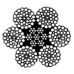
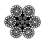




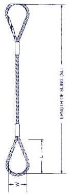
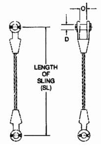
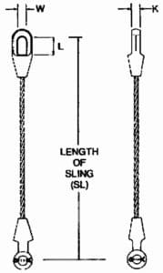
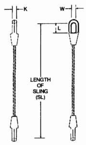
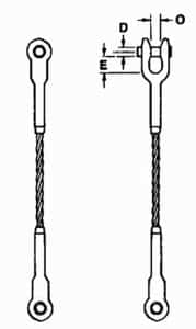
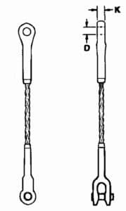
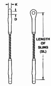
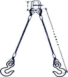
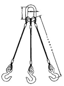
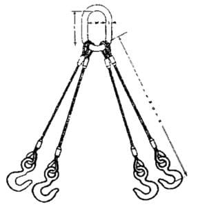
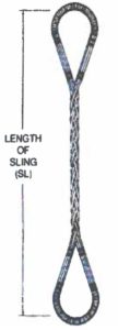
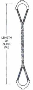
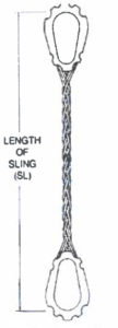


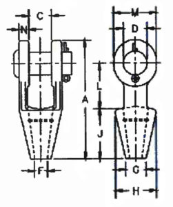
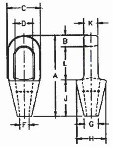
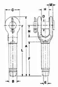
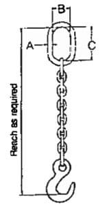


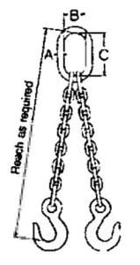
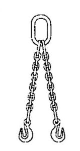
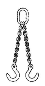
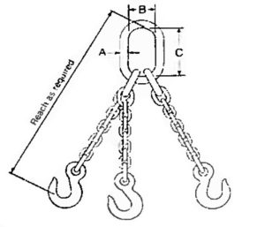
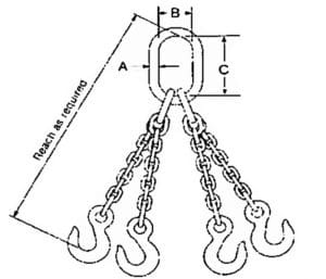
 Purple
 Green
Green
 Yellow
 Tan
Tan
 Red
Red
 Orange
 Blue
Blue
 Gray
Gray
 Brown
Brown
 Olive
Olive
 Black
Black
